TABLETOP WANDERING ROBOT
This tabletop wandering robot moves in all directions and uses infrared sensors to keep itself from falling off of tables by sensing changes in distance.
Engineer
Monica B.
Area of Interest
Computer Science (Artificial Intelligence)
Reflection
Overall, the experience of building a robot on my own was a tough but extremely rewarding one. I came into this program with the aspirations of learning more about electrical and mechanical engineering, as I was already familiar with software engineering. Specifically, I wanted to work with sensors because this is an aspect of Artificial Intelligence that I previously had no experience with and wanted to learn more about.
In terms of next steps, I plan to add another IR sensor to the back of the robot (and possibly more on the front & back sides for side movements) in order to keep the robot from falling off of a table back first. I would also like to add an ultrasonic sensor to the front to keep the robot from running into barriers. My original plan was also to add a camera in order for the robot to act like a driving drone; I plan to add this as well in the space holder at the front of the bot.
While I can confidently say that I’ve learned engineering in a way that no traditional lecture could have taught me, I am now aware of the type of engineering I want to pursue in the future: Computer Science. I faced challenges in all aspects of this project–from burning out three Arduino (microcontroller) boards before getting one to work with the servos and IR sensors to struggling with getting the chassi on time due to scaling and dimension issues. I’ve been opened to the troubleshooting required for all types of engineering. Although there are a number of problems that can–and will–occur in the process of building something, the outcome of a successful prototype is well worth the effort and all the failures in between make it that much more exciting when it does finally work.
Final Milestone
My final milestone consisted mainly of mounting the electrical components onto the chassi of the robot.
In order for the robot to successfully run, I had to find the correct height to place the front IR sensor because it only worked at a specific distance above the table–this ended up being about two inches.
While I had originally expected to use screws and washers to hold parts in place, I ended up relying a lot more on super glue, hot glue, velcro, and electrical tape to keep things together. There are wires all across the robot, maintained in their places with electrical tape. My battery, Arduino, and IR sensor PCB part were all attached to the robot with either velcro or some form of glue. I also added traction to the wheels by covering the edges with rubber bands.
Second Milestone
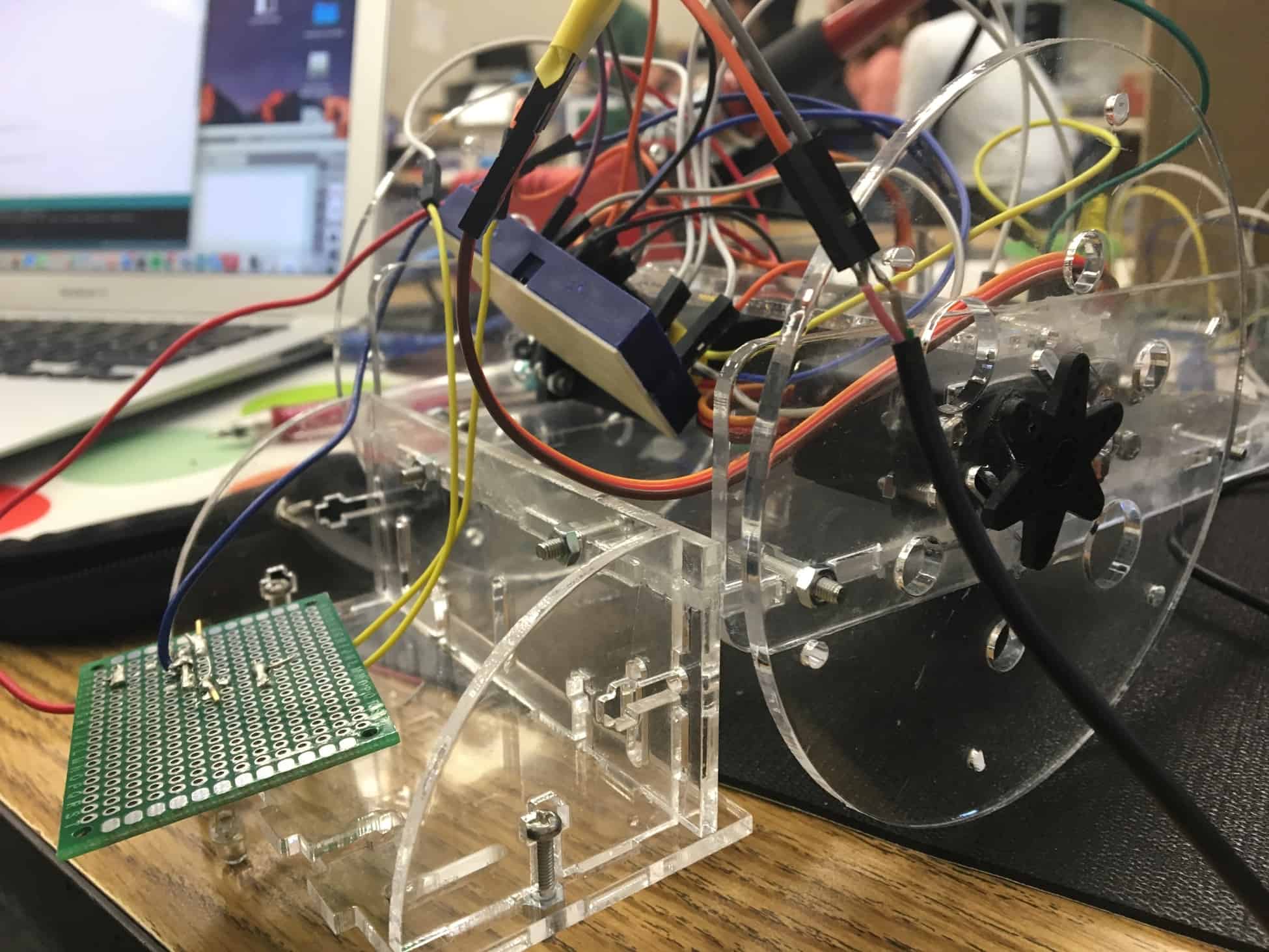
For my second milestone, I finished building the chassi of my robot as well as getting the infrared emitter and detector to run smoothly when reflected off of a surface.
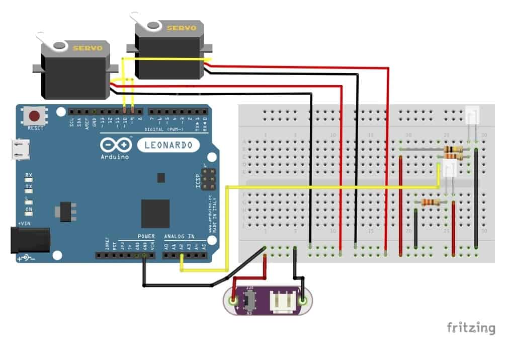
Switching from my previous milestone, I decided to use 3-pin detectors instead of the 2-pin ones because these are more sensitive to detecting infrared light, therefore they’re able to detect light when it’s reflected off of a table.
The 3-pin detectors are connected in series with a 330 ohm resistor, a digital pin, and a ground pin, while the emitters are connected in series with a 1k ohm resistor, a digital pin and a ground pin.
My chassi took a while to come, as there were many issues with the dimensions; after a getting all my electrical parts to work, the laser-cut acrylic pieces finally arrived and posed few challenges in being assembles.
My next step is to connect the sensor to the actual robot and get everything to run well together.
First Milestone
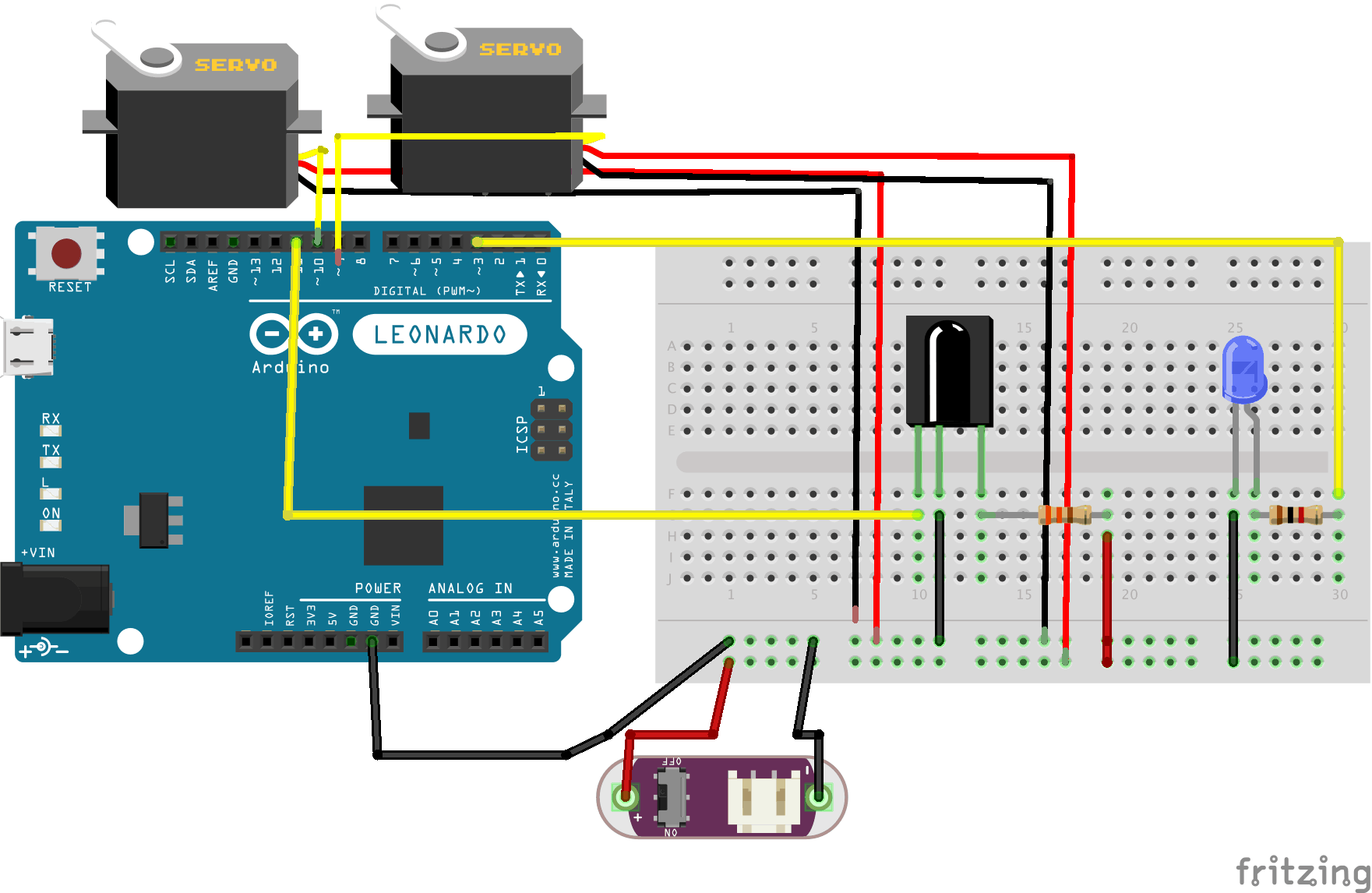
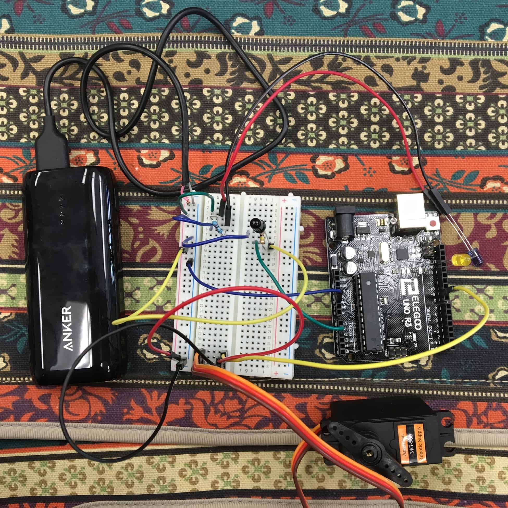
My first milestone in building my Tabletop Robot was getting an IR sensor, composed of an infrared emitter and detector, to get a servo to move. In doing this, I used a breadboard, Arduino Uno, IR emitter and detector, servo, resistors, external power source, and many, many jumper wires!
I created my schematic on Fritzing for the circuit, and then I built parts of it, coded on the Arduino IDE from scratch, and continued building until everything worked as expected. During this process, I first tested if the IR sensors worked by getting the pin on the Arduino to light up when the IR light was sensed by the detector and to turn off when it didn’t sense anything. I ran into many issues with this simple task, as I was getting a wide variety of readings from the detector, and my Arduino boards failed me multiple times because of overpowering-servos. After testing voltage across everything when a power source and servo were added to the circuit, I found that the IR detector needed to be directly connected to a 5V power source in addition to the digital pin it was attached so. I did so (using resistors of course, to regulate current), and I finally got the sensor to work! After this, I switched to an Arduino Uno, which would serve as my final controller board, and I modified code to turn the servo clockwise at the highest speed when the detector was in contact with IR light and counter-clockwise when not exposed.
From here, I plan to add more sensors and another servo, and then I will start working on the actual robot chassis!
Starter Project
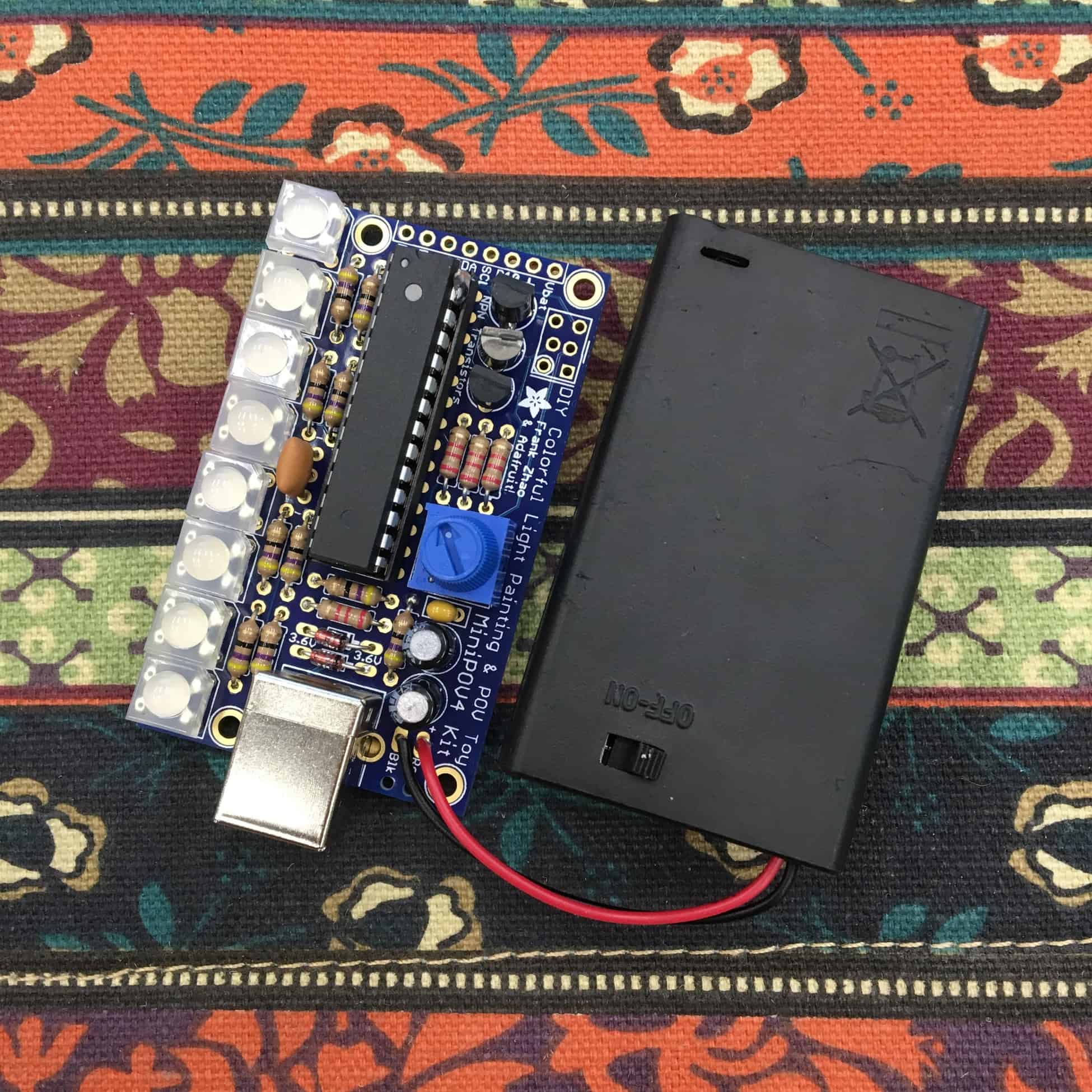
As a starter project, I build a Mini POV (Perception of Vision), which lights up in a certain pattern to show an image when moved back and forth horizontally. There were many components that went into building this, starting with the PCB, or printed circuit board, which is made of copper sheets and connective tracks to connect all the parts that go on it.
I first connected two types of resistors with different resistance amounts that regulate the amount of current that goes through the circuit. Then I added zener diodes, semiconductors that only let current go through them in one direction because they are polar, and transistors, which control the amount of current that flows through different parts of it, like a gatekeeper. The ceramic capacitors stabilize output voltage, while the electrolytic capacitors keep input and output voltage stable during upconversion–the process of light emission being controlled to a lower wavelength. Next, I attached the potentiometer, the meter that controls the speed of the LED light blinking by translating rotation into resistance, and the crystal, the timekeeper that keeps the LEDs at a constant speed.
Finally, the USB connector connects the computer to the microcontroller–which sits in the socket and stores information regarding the image that the LEDs are supposed to form when lit up. The LED lights in this model only express red, green, and blue, the three colors that computers express because the combination of any of them can form any visible color.