Creative Weather IOT Indicator

The weather IOT indicator that changes color based on the weather.

Engineer

Mone S.

Area of Interest

Mechanical Engineering, Electrical Engineering, Industrial Engineering, Engineering Design

School

Los Altos High School

Grade

Rising Junior

Reflection

This project was really fun to work on and I learned so much from it! Before coming into BlueStamp, I didn’t have any knowledge about engineering and was scared of not being able to understand the concepts or finish my projects. However, I was able to learn so much about the basic concepts of engineering in just one week! I’m still surprised about how much I learned because I learned so much! If I had more time, I would’ve drilled a hole in my plastic jar, so that the wires can go through it and would look a bit nicer. Overall, I am very happy that I chose this project because I now know how particle photons work and with that knowledge, I can build anything I want! I hope to apply the knowledge that I gained through this whole experience to future projects and build many amazing things! 

Third Milestone

For my final milestone, I soldered everything on a perfboard to make everything more permanent, so that the wires wouldn’t fall out. From this I learned that the perfboard isn’t connected unlike the breadboard, so you have to connect everything by soldering or using wires. I also decided to put everything in a jar with cotton in it to make it more aesthetically pleasing. The reason why I chose this project was that I wanted to learn more about how the code, the information from the cloud, and the hardware works together. From this, I was able to learn exactly what I wanted and it was very interesting to learn about particle photons, IFTTT, the neopixel and many more. One of the challenges I had was connecting the particle photon to the cloud and seeing if the IFTTT is working. In the beginning, I thought that my IFTTT wasn’t sending information to my particle because the neopixels weren’t lighting up. I eventually figured out that the applets I created on IFTTT tell the neopixel to change color only when the weather changes, so I decided to create a new applet where it changes color when it’s a certain time. Although, for the applet I created, I didn’t know what the possible conditions that the IFTTT was giving, so I had to create a particle variable to find out what the return values of the IFTTT were. Another challenge I faced was connecting the particle to the cloud. Although it took some time and some help from the instructors, I was able to connect it to the cloud and get my project going. Overall, I am very happy with how my project turned out and plan to make more modifications individually. Now that I understand how the particle photon functions, I hope to use the skills I learned at bluestamp engineering and do many projects using a particle individually and do amazing things with it!

Second Milestone

screen-shot-2019-06-15-at-9.44.15-pm
screen-shot-2019-06-15-at-9.44.32-pm
screen-shot-2019-06-15-at-9.44.44-pm
screen-shot-2019-06-15-at-9.44.50-pm
screen-shot-2019-06-15-at-9.45.04-pm
screen-shot-2019-06-24-at-6.38.19-pm

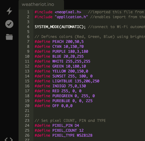
My second milestone was coding everything on particle, so that the information from IFTTT gets sent to the photon and make the neopixel light up based on the weather. Another thing I did was create an applet on IFTTT so that the code can take in certain conditions. For the code, I coded everything on particle since the hardware I used was the particle photon.

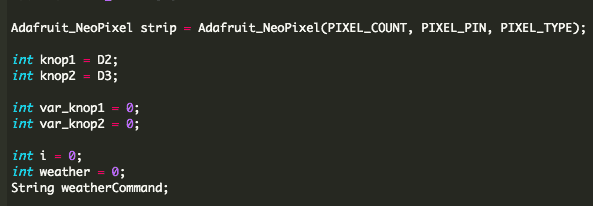
Library, Defining and Variables: I first uploaded files from the particle library which are precoded files for whatever you need. Since my project uses a neopixel, I uploaded the neopixel file. For all projects that require you to use the library files, application.h is needed since this code allows you to import files from the library and function. SYSTEM_MODE(AUTOMATIC), makes the photon into an automatic mode so that it will try to connect to Wi-Fi automatically. After that, I defined all the colors by assigning each color a specific brightness. For example, for my PEACH color, I made the brightness 200 for the red LED, 50 for the green LED and 5 for the blue LED. This makes sense since the peach color is most similar to red. Just like I defined all the colors, I also defined the information of the pixels, which are the pin, the number of pixels and the type. That way, I can assign values to the neopixel to use it later in my code. “knop” is an int variable I created I which is connected to the D2 and D3 pins on the photon. I also created variables called var_knop and weather and set those values equal to 0. I created those variables early in the code, but used it later.

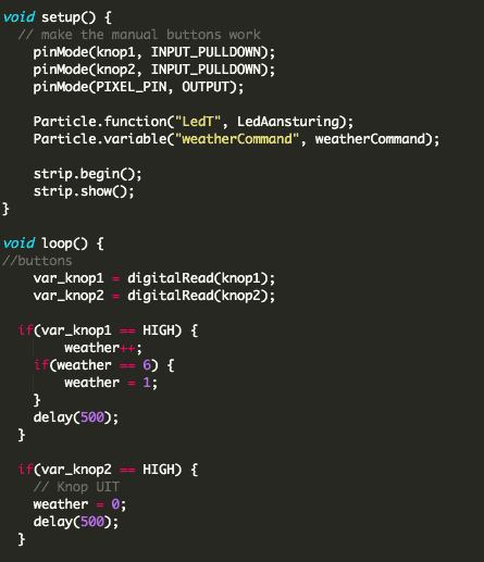
Void Setup: Next, I have my void setup, where I wrote code for information that only needs to be run or put into the system once before it goes into the loop. Since it’s a void, it doesn’t return a value. In my void setup, I have a code that says, pinMode, which makes a pin to behave as an input or an output. In this case, the digital pins are used as INUT_PULLDOWN, which means that the input pin will be LOW when the switch is open and HIGH when the switch is closed. This concept is also used later in the code where I have digitalRead written.  After that, I have the particle.function, which allows the code to be run when it’s requested from the cloud, in this case, from weather underground. Below that, I also created a particle variable, which is a way to debug the system. I used this because I didn’t quite know what the IFTTT was returning as a condition, so I typed this in to find out on the particle website, that way, I can set my command variable in my method. Finally, the strip.begin(); prepares data pin for the neopixel output and strip.show(); makes all the pixels to be ‘off’.

Void Loop: The void loop is a loop, meaning that it will keep running the code over and over again until it reaches a certain value or when it tells itself to stop. Again, since it’s a void, it doesn’t return a value. In my void loop, there are two parts. The first part is where I make the buttons function and the second part is where I have the color changing based on the weather.

  1. Buttons: To make the buttons function, I first set the variables var_knop to digitalRead with an input called knop, which is a variable I previously made. What the digitalRead does is it reads if the voltage is HIGH or LOW from the pin. In this case, since the power is supplied from the 3v3, it will return HIGH when the circuit has 3.3 volts. This means that before the buttons are pressed, it has an open circuit, so there is no voltage going through it and will return the value of LOW. However, when the buttons are pressed, the circuit will close and the voltage will go through, changing the return value to HIGH. After the digital read,  I have an “if statement” where if the return value is HIGH, I change the value of the variable weather by 1. This is why the neopixel lights up every time I press the button and changes color. Since I only have 6 maximum weather conditions and colors, I coded it, so that once the buttons are pressed more than 6 times, it’ll go back to the first color and will continue to change colors. I also put the word “delay” with a number. What the delay does is it just waits for however many milliseconds you put, so that when the buttons are pressed, the color is visible and doesn’t change super fast. For the other button, I coded it, so that when the digitalRead is HIGH, or when the buttons are pressed and voltage is going through, the weather will be equal to 0, which will stop the neopixel from lighting up.
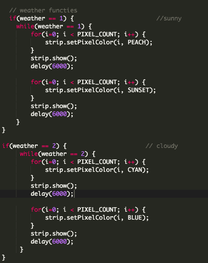
  2. Weather Conditions: This is where I used a variable I created called weather a lot. This code also explains why when the buttons are pressed and an int variable, weather is set to 0 through 6, it changes color. There are 6 different if statements,  one for each color. Once the variable, weather is equal to a certain integer, it changes color based on what the value is. For example, if the button is pressed once, the weather value will be equal to 1, changing the neopixel color to the color assigned to weather = 1, which is PEACH and SUNSET.
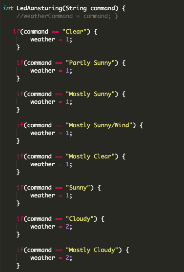
  3. Weather Method: Part of the reason why the if statements works are because of this weather method called LedAansturing that I created. This method is where it takes in the condition from the IFTTT and based on what the condition is, it changes the value of the weather to a certain value. For example, if my applet from the weather underground returns the value of “Clear”, the weather value will be set to 1, which then goes up to the code I previously wrote and will change color to PEACH and YELLOW.

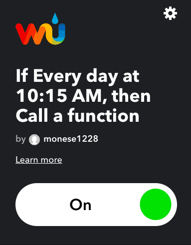
Setting my Applet: Another thing I had to do for my project was to set up my applet on IFTTT. Since this was a weather indicator, I chose the weather underground service and for my trigger, I chose “Today’s weather report”. I originally chose a trigger called “Current condition changes to”, but I realized that for that certain trigger, it will only tells the code to change color only when the weather changes. Since that is not what I wanted, I chose the “Today’s weather report” for my trigger. In the trigger, I set the location and the time, so that my neopixel will light up based on when and where I wanted. Then, for my action service, I chose the particle, so that the particle will take in information from IFTTT and make the neopixel change color based on the information from the weather underground.  

Overall: Overall, this part of my milestone was successful since I had a little bit of coding background from taking an intro to computer science course at my school. I was able to make many different modifications in my code of which colors I wanted the neopixel to light up, as well as how I wanted it to light up. For some conditions, I made the light to flash, while for others, I made it so that it changes between two colors every 30 seconds or so. I was also able to have a certain pixel to light up in one color, while others in other colors. For example, I made it so when the weather is a thunderstorm, it will light up in a rainbow color, making every pixel to have a different color. I was very happy with the fact that coding on particle was very similar to java and I was able to understand mostly everything without research. It was also very cool to learn about specific functions for particle like particle.function and digitalRead. I also didn’t know about particle libraries, so learning about that was also very interesting.

First Milestone

My first milestone was building and putting together the physical parts and planning out the circuit on the breadboard. Neopixel: One of the important components I used was the neopixel. Neopixel is a circular ring containing 12 pixels, which is responsible for the light and the color of my project. Inside of each pixel, it contains 3 LEDs which are red, blue and green. You can control the color of each LEDs by changing the brightness of each color, which ranges from 0-255 since it has an 8-bit address. Particle Photon: Another important component is the particle photon, which is a microcontroller that gets information from the cloud. Without this, the color of the neopixel will not change based on the weather underground from the IFTTT. Breadboard and Circuits: On the breadboard, there are 3 small circuits. The first circuit gets the power from the V-IN, which is part of a photon. Since the power rails on the breadboard are connected vertically, the power gets carried to the red wire. Because the red wire is soldered onto the power receiver on the neopixel, it uses the power to light up the LEDs. After that, the circuit goes to the ground, creating a full closed circuit. The second circuit gets the power from the 3v3, where the grey adapter is connected to. Then, the power from the 3v3 is connected by the connectors, which is connected to the buttons, which is connected to the adapters that are connected to the D2 and D3. I coded this on particle to control what the D2 and D3 do, which is making the buttons function. The third circuit only contains two components. It starts with D4 from the photon being connected to the yellow wire that’s soldered through the Data In on the neopixel. The reason why the yellow wire and the adapter attaching to D4 are connected is because the terminal strips on the breadboard are connected horizontally. In the second milestone, I will code on particle, so that D4 will send information from the IFTTT to the neopixel and light up in different colors based on the weather. Challenges: In this milestone, one problem I had was the neopixel not lighting up. Eventually, I figured out that I soldered the wires through Data Out instead of Data In. From this, I learned that Data In takes in data, while data out takes out the data. An example of a time where you would use data out is when you have multiple neopixels lining up and want them to light up one by one. In that case, one neopixel will send data out to another, meaning that the wires will have to go through data out. However, since that is not the case for my project, I learned that I had to put the wires through Data In and not Data out. Another problem I had was that the wires kept breaking, so I had to desolder many times. Desoldering this was not easy since the wires got in the way from me melting the solder with the soldering iron and using the pump. Since I didn’t want to keep desoldering every time the wires fell out, I solved this by applying hot glue to the wires, so that it won’t break as easily.

Simon Says

screen-shot-2019-06-24-at-6.50.52-pm
screen-shot-2019-06-24-at-6.51.00-pm
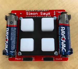
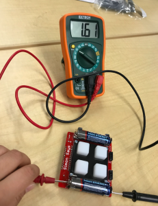
For my starter project, I did Simon Says. I chose this project because I wanted to learn about circuits and electricity, as well as how to solder. In the game, there are many components such as the ATMega microcontroller, the Buzzer, the 0.1μF Cap, the 10K Resistor and the LEDs. ATMega microcontroller is like the brain of the game, where the game was programmed into, so it can tell other components to do certain things. For example, when the button is pressed by the user, the microcontroller will tell the LEDs to light up again. The black circular object is called the buzzer, which is responsible for making sounds. The buzzer contains 2 pins and on the inside, it has a piezo element, which is a central ceramic disk surrounded by a metal vibrating disk. Once the current is applied to the buzzer, the ceramic disk expands or contracts, making the disk around it to vibrate, which is the sound that we hear. The pitch of the sound can be controlled by changing the frequency, which can be controlled by changing the voltage. The 10K resistor is used to resist and limit the amount of current. The reason why limiting the amount of current is needed is because some components such as the LED lights and the ATMega microcontroller cannot function with a high current. The 0.1μF Cap maintains a power supply. The LEDs are used to light up the pads and the battery clips are used to hold the batteries in place. Another important components are the batteries and switches. The battery provides power for the circuit. This game specifically requires 2 batteries because else, it doesn’t have enough voltage for the whole circuit to work. The switches are used to open or close the circuit. One of the switches is used for the lights and the other is used for the sounds, that way, you can choose to play the game without sounds. I found out that this is a series circuit using the multimeter. To use the multimeter I first had to figure out if the circuit is direct or alternating current. Since most of the circuit contains a direct current except for things like the power outlet, I used the direct current sign when I used the multimeter. Then, I measured the voltage of one battery using the multimeter and found out that it was 1.6 V. Then I measured the opposite end of the batteries and found out that it was 3.2 V. Since 2 x 1.6 = 3.2, I know that it’s a series circuit since series circuit is a circuit where the resistors are arranged in a chain, making the current to have only 1 path to take. Other components of this game are the button pads, which is a rubber pad that goes over the LEDs as well as the bezel, which hold the pads. The screws hold the pads and the bezel together in place, while the standoffs hold the screw in place. Some things that I was surprised with is how one small thing can affect the whole project. For example, I had no idea that the shorter side of the LED is negative and the longer side is positive. Before I built this game, I had never paid attention to a LED before and I didn’t know that the length of the legs mattered. By putting the wrong leg into a hole, the project cannot function. From this, I learned that you have to be careful and pay close attention to small details when putting parts together. Before I started this project, I had zero experience with engineering, but I was able to learn about basic circuits and components used for many projects like the resistors and the microcontroller. Doing this starter project was a great way to get introduced to basic engineering concepts and I hope to apply the things I learned to my main project.

STEM Summer Camps Coding & Robotics Classes For Kids San Francisco Coding & Robotics Classes For Kids New York Coding & Robotics Classes For Kids Denver Coding & Robotics Classes For Kids Palo Alto STEM Summer Camps For Kids in New York STEM Summer Camps For Kids in Palo Alto STEM Summer Camps For Kids San Francisco STEM Classes For Kids in New York STEM Classes For Kids in Palo Alto STEM Classes For Kids in San Francisco Code Classes For Kids Code Classes For Kids in New York Code Classes For Kids in Palo Alto Code Classes For Kids in San Francisco STEM Summer Camps For KidsSTEM Summer Camps Coding & Robotics Classes For Kids San Francisco Coding & Robotics Classes For Kids New York Coding & Robotics Classes For Kids Denver Coding & Robotics Classes For Kids Palo Alto STEM Summer Camps For Kids in New York STEM Summer Camps For Kids in Palo Alto STEM Summer Camps For Kids San Francisco STEM Classes For Kids in New York STEM Classes For Kids in Palo Alto STEM Classes For Kids in San Francisco Code Classes For Kids Code Classes For Kids in New York Code Classes For Kids in Palo Alto Code Classes For Kids in San Francisco STEM Summer Camps For Kids

Leave a Comment

Start typing and press Enter to search

Bluestamp Engineering