The Pipe Robot
Hi, I am Miles, and I am building a Pipe Robot for my main project at Bluestamp, a STEM summer camp program in NYC. This robot consists of an Arduino nano connected to two motors which are placed inside a PVC pipe. I will try to control the robot through Bluetooth.
Engineer
Miles K.
Area of Interest
Computer Science Engineering
School
Ramaz
Grade
Incoming Junior
Reflection
Before I came to BlueStamp, I had no knowledge of engineering. Only a little coding. BlueStamp taught me to do everything on my own without asking for plenty of help. Over the summer, I learned a lot about code and how it is very confusing sometimes. Engineering is a great field for me because I like fixing things with my hands and mind. I took this opportunity to realize that in the future, I want to pursue computer science engineering or cybersecurity.
Final Milestone
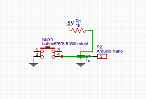
After achieving my third milestone, I added more to my routine and a button to start my robot. I added right and left turns to my little demo routine. After pressing the button that I created, it restarts the code that I programmed onto the Arduino Nano. For this button work, I used an interrupt. An interrupt is a signal to the processor emitted by hardware or software indicating an event that needs immediate attention. The button that I inserted is a hardware interrupt for the robot to start the routine again. Look at the diagram above for the circuit schematic of the interrupt. An interrupt alerts the processor to a high-priority condition requiring the interruption of the current code the processor is executing. Through this main project, I learned a lot about coding and figuring things out on my own. What is next is to try making the Pipe Robot compatible with either Bluetooth or WIFI.
This is the code for the whole routine that I created:
Code for interrupt:
pinMode(2, INPUT);
pinMode(3, OUTPUT);
digitalWrite(3, HIGH);
attachInterrupt(digitalPinToInterrupt(2), rst, FALLING); // the pressing of the button completes the circuit
Code for the reset, to start the routine that I programmed again:
void rst(){
Serial.println(“reset”);
onoff = !onoff;
Serial.println(onoff);
}
Code for the motors to move forward:
void foward(){

  digitalWrite(in1, LOW);

  digitalWrite(in2, HIGH);

  digitalWrite(in3, LOW);

  digitalWrite(in4, HIGH);

}
Code for the motors to move backward:
void backward(){

  digitalWrite(in1, HIGH);

  digitalWrite(in2, LOW);

  digitalWrite(in3, HIGH);

  digitalWrite(in4, LOW);

}
Code for motors to turn right:
void turn_right(){
digitalWrite(in1, LOW);
digitalWrite(in2, HIGH);
digitalWrite(in3, HIGH);
digitalWrite(in4, LOW);
}
Code for motors to turn left:
void turn_left(){
digitalWrite(in1, HIGH);
digitalWrite(in2, LOW);
digitalWrite(in3, LOW);
digitalWrite(in4, HIGH);
}
Code for motors to suddenly stop:
void brake(){
digitalWrite(in1, LOW);
digitalWrite(in2, LOW);
digitalWrite(in3, LOW);
digitalWrite(in4, LOW);
}
The code below programs a loop for the motors. For the code that I created, the robot is able to move in each direction:
void loop()
{ while(onoff){
foward();
delay(10000);
backward();
delay(5000);
turn_left();
delay(7000);
turn_right();
delay(8000);
brake();
delay(5000);
onoff = false;}
//demoTwo();
//delay(1000);
Serial.println(“Wheels are turning”);
}
Third Milestone
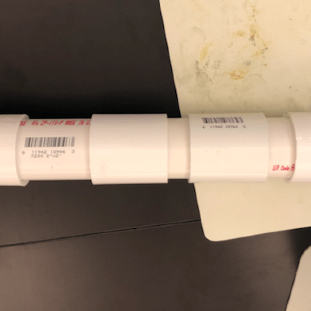
For my third milestone, I fully constructed made robot made out of PVC pipe and programmed a little demo routine. The robot moves forward and backward according to the way I programmed the Arduino Nano. The code below programs the DC motors to move forward. This code controls which way the motors should move.
The code below programs the DC motors to move forward. These codes control which way the motors should move.
void foward(){
digitalWrite(in1, LOW);
digitalWrite(in2, HIGH);
digitalWrite(in3, LOW);
digitalWrite(in4, HIGH);
}
The code below programs the DC motors to move backward.
void backward(){
digitalWrite(in1, HIGH);
digitalWrite(in2, LOW);
digitalWrite(in3, HIGH);
digitalWrite(in4, LOW);
}
The code below programs a loop for the DC motors, to allow the code that I created for backward and forward to keep spinning.
void loop()

{ while(onoff){

  foward();

  delay(10000);

  backward();

  delay(5000);

}
The robot consists of an Arduino Nano, which is a microcontroller, and a motor shield, which controls the speed and direction of both DC motors. I used a portable ANKER charger to both power the Nano and the motor shield. I also used a hacksaw to evenly cut the PVC pipe to fit all of the components that I used into the pipe. I drilled four holes on both ends of the pipe to screw in the motors so they would not fall off when moving. Over this summer, I overcame many difficulties that I had including the motors not working. I figured out that the screws were too tight which did not allow the motors to move. Once I realized, I loosened the screw and the DC motors were working the way I wanted it. Through building this robot, I learned more about programming on my own rather than someone helping me. What’s next for this project is to build a button that would start a routine with twists and turns.
Second Milestone
Figure 1: Shows how the wheels are put on.


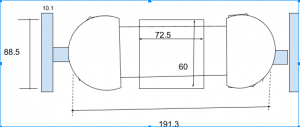
Wheels of the Pipe Robot
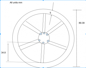
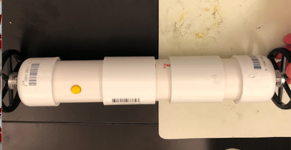
Figure 2: All components in the Pipe Robot.


Pipe Robot Full Body
For my second milestone, I placed all the components in the pipe robot and connected the motor shield to the Arduino. The motor shield is used for extra functionality like controlling the directions and has an H-bridge. First, I got the wheels on the motors. I drilled 4 holes into the caps of the robot, and then screwed in the motors so that they can stay in placed while the pipe robot is moving. Then, I put all of the components into the robot. The components are the motor shield, Arduino, and motors. My biggest challenge was to get the power through the motor shield on the Arduino without using my computer. I will eventually connect a power supplier to power the Arduino. I first tried changing the wires to see if it was a connection issue, but it was not. Then I used the multimeter to see if there was enough power. I turned the multimeter to measure the voltage of the motor shield. I put the black wire onto ground and the red wire onto 5V, but there was enough voltage being supplied. But it was still not working. Then I thought about switching the motors between each side of the motor shield to see if the shield was not working, but that was not the problem. I thought that if I switched the motors between each side, it would be the motor’s fault. I finally found out that the motor shield was not connected to a common ground on the Arduino. All components in a circuit must have a common ground because of the voltage difference. I used the same circuit from my first milestone. Refer to my first milestone section for a full schematic. The power supply, with an outlet, was also not giving the Arduino enough voltage to move both motors. I used a power supply box to give the robot enough power to move both motors.
First Milestone
Figure 1: The L289N motor shield.
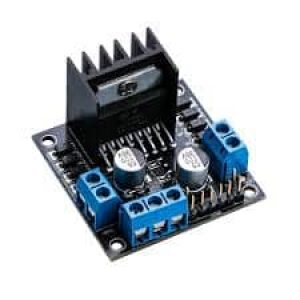
Figure 2: The schematic of setting up the motors.
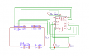
The schematic above (figure 2) shows how I wired the motors to the Arduino and motor shield. The code below tells the Arduino to connect the motor controller pins to the Arduino digital pins, and tells it what pins are connected to the motor shield. Every motor has the same number of pins to connect to the Arduino. Each one has three pins: an enable pin (tells H-bridge to turn the motor on and off), and two input pins (when set to high, the switch closes, but when set to low, the switch opens).
{
// motor one
int enA = 10;
int in1 = 9;
int in2 = 8;
// motor two
int enB = 5;
int in3 = 7;
int in4 = 6;
}
The code below will run the motors in both directions at a fixed speed. The motors are being told to move forward and backward. When the polarity changes, it allows the motors to change directions. The H-bridge tells the motors to turn on and off for a certain amount of time.
// this function (demoOne) will run the motors in both directions at a fixed speed // now change motor directions
// turn on motor A
digitalWrite(in1, HIGH);
digitalWrite(in2, LOW);
// turn on motor B
digitalWrite(in3, HIGH);
digitalWrite(in4, LOW);
// now turn off motors
digitalWrite(in1, LOW);
digitalWrite(in2, LOW);
digitalWrite(in3, LOW);
digitalWrite(in4, LOW);
Serial.println(“motors off”);
}
This is how the demoOne is being programmed to run with a delay of 10 seconds.
void loop()
{
demoOne();
delay(1000);
}
Full Code below:
// connect motor controller pins to Arduino digital pins
// motor one
int enA = 10;
int in1 = 9;
int in2 = 8;
// motor two
int enB = 5;
int in3 = 7;
int in4 = 6;
void setup()
{
// set all the motor control pins to outputs
pinMode(enA, OUTPUT);
pinMode(enB, OUTPUT);
pinMode(in1, OUTPUT);
pinMode(in2, OUTPUT);
pinMode(in3, OUTPUT);
pinMode(in4, OUTPUT);
Serial.begin(9600);
}
void demoOne()
{
// this function will run the motors in both directions at a fixed speed
// turn on motor A
digitalWrite(in1, HIGH);
digitalWrite(in2, LOW);
// set speed to 200 out of possible range 0~255
digitalWrite(enA, HIGH);
// turn on motor B
digitalWrite(in3, HIGH);
digitalWrite(in4, LOW);
// set speed to 200 out of possible range 0~255
digitalWrite(enB, HIGH);
Serial.println(“both motors on”);
delay(10000);
// now change motor directions
digitalWrite(in1, LOW);
digitalWrite(in2, HIGH);
digitalWrite(in3, LOW);
digitalWrite(in4, HIGH);
Serial.println(“Motors reverse”);
delay(10000);
// now turn off motors
digitalWrite(in1, LOW);
digitalWrite(in2, LOW);
digitalWrite(in3, LOW);
digitalWrite(in4, LOW);
Serial.println(“motors off”);
}
void demoTwo()
{
// this function will run the motors across the range of possible speeds
// note that maximum speed is determined by the motor itself and the operating voltage
// the PWM values sent by analogWrite() are fractions of the maximum speed possible
// by your hardware
// turn on motors
digitalWrite(in1, LOW);
digitalWrite(in2, HIGH);
digitalWrite(in3, LOW);
digitalWrite(in4, HIGH);
// accelerate from zero to maximum speed
for (int i = 0; i < 256; i++)
{
analogWrite(enA, i);
analogWrite(enB, i);
delay(20);
}
// decelerate from maximum speed to zero
for (int i = 255; i >= 0; –i)
{
analogWrite(enA, i);
analogWrite(enB, i);
delay(20);
}
// now turn off motors
digitalWrite(in1, LOW);
digitalWrite(in2, LOW);
digitalWrite(in3, LOW);
digitalWrite(in4, LOW);
}
void loop()
{
demoOne();
delay(1000);
//demoTwo();
//delay(1000);
}