Injury Predicting Shoe
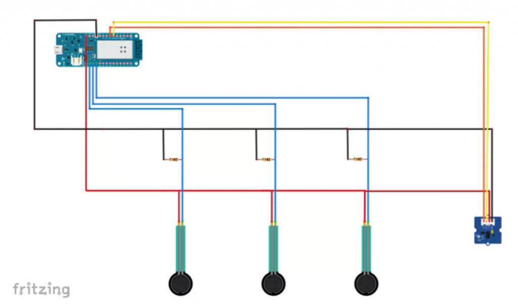
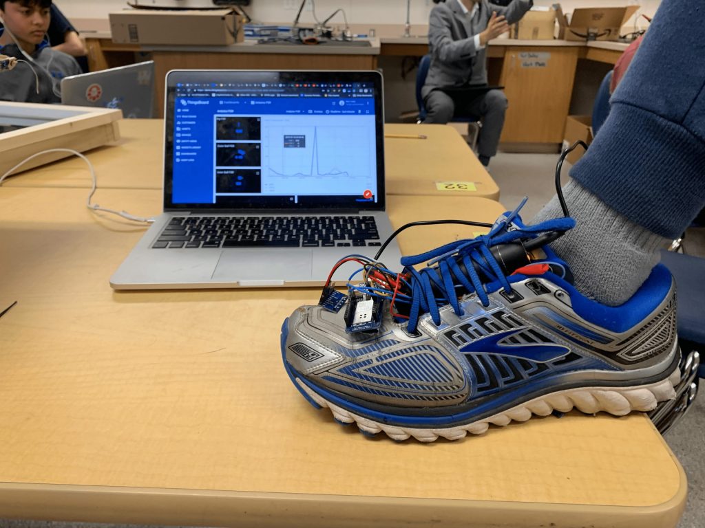
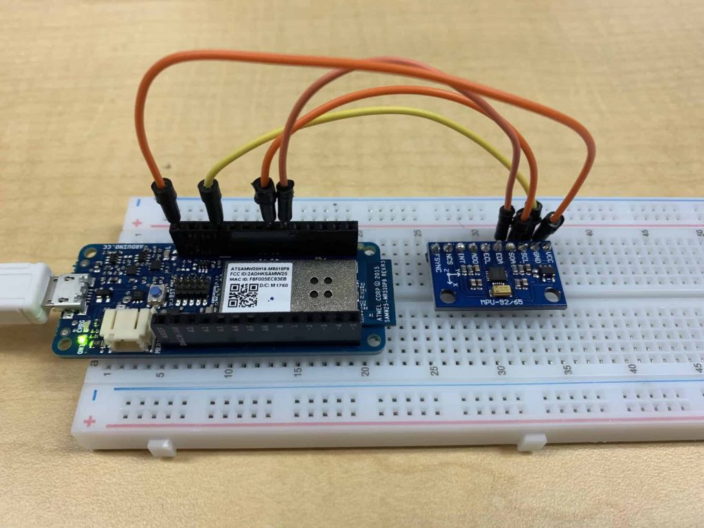
For my main project, I chose to make a shoe that tracks running form and predicts injuries. I will use pressure sensors and accelerometers to get the data while the user runs.
Engineer
Mihir H
Area of Interest
Software Engineering
School
Saint Francis High School
Grade
Rising Junior
Schematics
Final Milestone
Third Milestone
Second Milestone
First Milestone
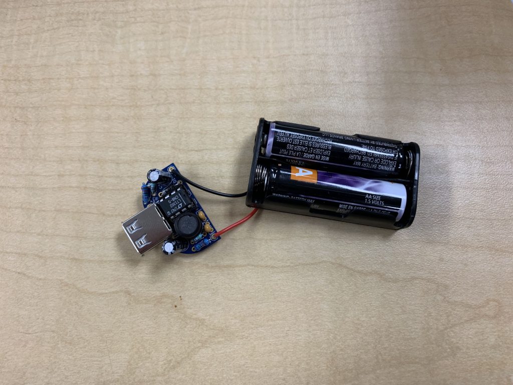
Starter Project