FM Radio
Hi! My name is Mia and I am a rising sophomore at SAR High School. For my starter project, I built a MintyBoost, which is a battery powered portable charger for your cell phone or any other device that connects through a USB cable. Then, for my main project, I constructed a monophonic Frequency Modulation (FM) receiver that accepts FM signals in the frequency range 88-108 MHz. I chose both of these projects because they would give me a hands on introduction to engineering and increase my knowledge of the electronic parts on a circuit board, such as resistors, capacitors, transistors, semiconductors, and more.
Engineer
Mia G
Area of Interest
Electrical and Mechanical Engineering
School
SAR High School
Grade
Rising Sophmore
Reflections
MATERIALS:
Final Milestone


Second Milestone
For my second milestone, I completed my first modification, which was designing an acrylic plexiglass showcase for the housing of my radio. One of the challenges I encountered was developing a design that would allow the radio to be secure in a protective framework while also allowing the switches and knobs of the radio to be viewable and accessible from the outside. I also had to create a way for the sound to travel out of the radio. After marking the plexiglass with a thin sharpie and lining up my ruler along the plexiglass using alligator clips, I worked with many tools, such as a plastic cutter tool with a sharp steel blade and a dremel, to cut the two pieces of plexiglass I needed for the front and back of my showcase. Using the dremel allowed me to quickly and efficiently cut clean straight lines in the plexiglass, while the cutter was much more time consuming and required a greater amount of force. I would recommend using a dremel when recreating this project. I sanded down the edges of the plexiglass using sandpaper and files to make them smooth and sleek. I took a drill and, lining up my front and back sheets, I created four holes to insert standoffs so that there would be room for me to place the radio in between the two pieces of plexiglass. I drilled three additional holes in my radio, making sure not to interrupt the circuit, and then I made those same holes on the back sheet of plexiglass. I used more standoffs to mount my radio in between the two sheets of plexiglass so it would not fall down through the bottom. After, I drilled a circular hole for the knob and a rectangular hole for the two push button switches so that they would be accessible from the front of the radio. I filed the holes to get rid of the jagged edges and make the insertions polished. Then, I stepped back and admired the smooth finish and clear viewing of my radio in the showcase. I came across a few complications during this process, such as creating some scratches in my plexiglass, damaging a few pieces of plexiglass, and making uneven holes with the drill, but I was able to overcome all of these obstacles. Another difficulty I faced was that the knob on the potentiometer, which turns on the radio and adjusts the volume, was too short and small to be reached from the outside. I am in the process of modeling a 3D printed knob to act as a replacement for the knob on the potentiometer to expose the dial and make it usable. I am adding my name on the dial as a personal touch to make my radio unique. Overall, I am happy with my final project and the new skills I acquired.
First Milestone
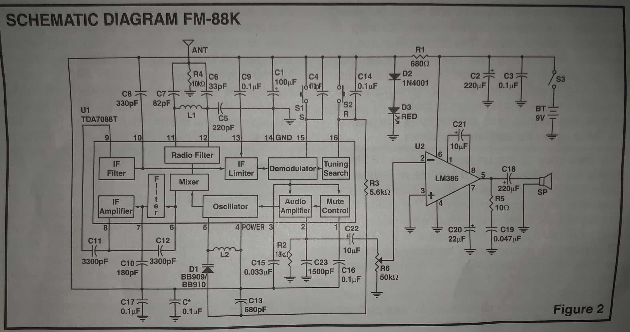
For my first milestone, I finished building my radio by installing all of the electronic parts to the PC board and testing my radio to make sure it functions correctly. This monophonic Frequency Modulation (FM) receiver accepts FM signals in the frequency range 88-108 MHz. This FM radio uses an electronic auto- scan to search for FM stations and it is operated by two push button switches. The two switches are scan “S” and reset “R.” The circuit contains two ICs (one for the audio section and one for the radio frequency), a 9V battery as the power source, an antenna to radiate and pull signals, an 8Ω speaker to give off audio, a potentiometer to control volume, and a few other components. I started by soldering various resistors, capacitors, semiconductors, and coils to the PC board. Resistors, such as the 50kΩ (Ohms) Potentiometer, are electronic components that resist the flow of electricity. Capacitors, both discaps and electrolytic radials, are electronic components that store current and block the direct current, which only flows in one direction. Diodes are electrolytic components that change alternating current and direct current. A varactor is a diode that changes its internal capacitance depending on the applied voltage. Coils, such as 4-turn coils and 6-turn coils, have inductive reactance, which is what an inductors electrical resistance is called when used in an alternating current circuit. They receive and transmit radio frequency signals. Next, I mounted my red LED to the PC board, which is a diode that gives off light when voltage and current are passed through it. I attached my IC socket and inserted my IC chip into the socket. This IC is an LM386 amplifier, a low voltage audio power amplifier. In order to make the amplifier more versatile, two pins are provided for gain control and adjustments. 1.35kΩ resistors set the gain at 20 when pins 1 and 8 are open, but the gain can go up to 200 if a capacitor bypasses the 1.35kΩ internal resistors when it is placed in between pins 1 and 8 . The amount of gain control, or signal multiplication, changes based on the potentiometer which varies audio level and volume. I installed my battery holder and speaker and soldered the speaker wire to the pads +SP and -SP. To test my radio, I installed a new 9V battery in the battery holder, extended my antenna, turned the power switch on the potentiometer to on, and turned the knob fully clockwise. The LED lit! Next, I pressed the reset button and the scan button a couple of times until I heard a station. Pressing the scan button allows you to search for other broadcasting stations. The tuning on the radio is done using a varactor diode and the varactor capacitance is changed by altering the DC voltage supplied to its anode over resistor 3. Station signals are led from the telescopic antenna to the input circuit and inside the IC, signals are led into a mixer. There they are given a new carrier intermediate frequency. The IF amplifier only amplifies one of these signals: the one whose frequency is equal to the IC. Then follows the limiter, demodulator, mute control circuit, and pre audio amplifier, which all affect the sound and the frequency of signals. Some problems I faced were that when I first turned on my radio, I didn’t hear any sound. After checking the position of the parts, the solder joints, the voltage, and the continuity, I discovered that the problem was that the IC chip for the audio section of my radio was dead. I needed to order a new LM386 and desolder my old IC socket in order to fix this problem. Another problem I faced was that I had trouble soldering one of my parts and I lost the connection on the PC board when I burnt off the solder joint and socket. I had to attach an extra wire along the top of two solder joints in order to restore the continuity. The sound wasn’t clear when I turned on my radio, so I installed capacitor C* onto the copper side of the PC board on top of the radio frequency IC to improve the sound. I added an extra capacitor because a capacitor blocks all direct current and passes only alternating current, a type of electrical current that continuously changes direction, including audio. Capacitors can take up, store, and release electrical energy fairly quickly so they are used to filter any abrupt changes in circuit voltage and filter out high frequency noises, which smooths the signals.There are many differences between AM, Amplitude Modulation, and FM, Frequency Modulation, radios. AM signals vary their amplitude to adapt to the sound information that is transmitted through the wavelengths, and these changes are very noticeable because they result in audible static. In an FM radio, sound is transmitted through changes in frequency and changes in amplitude are much less noticeable. When you switch between broadcasts on an FM radio, the antenna is switching between different frequencies and amplitudes which produces better sound and less static in transitions. I was so happy that, despite a few complications, I successfully completed my radio!