Final Milestone

Second Milestone

First Milestone
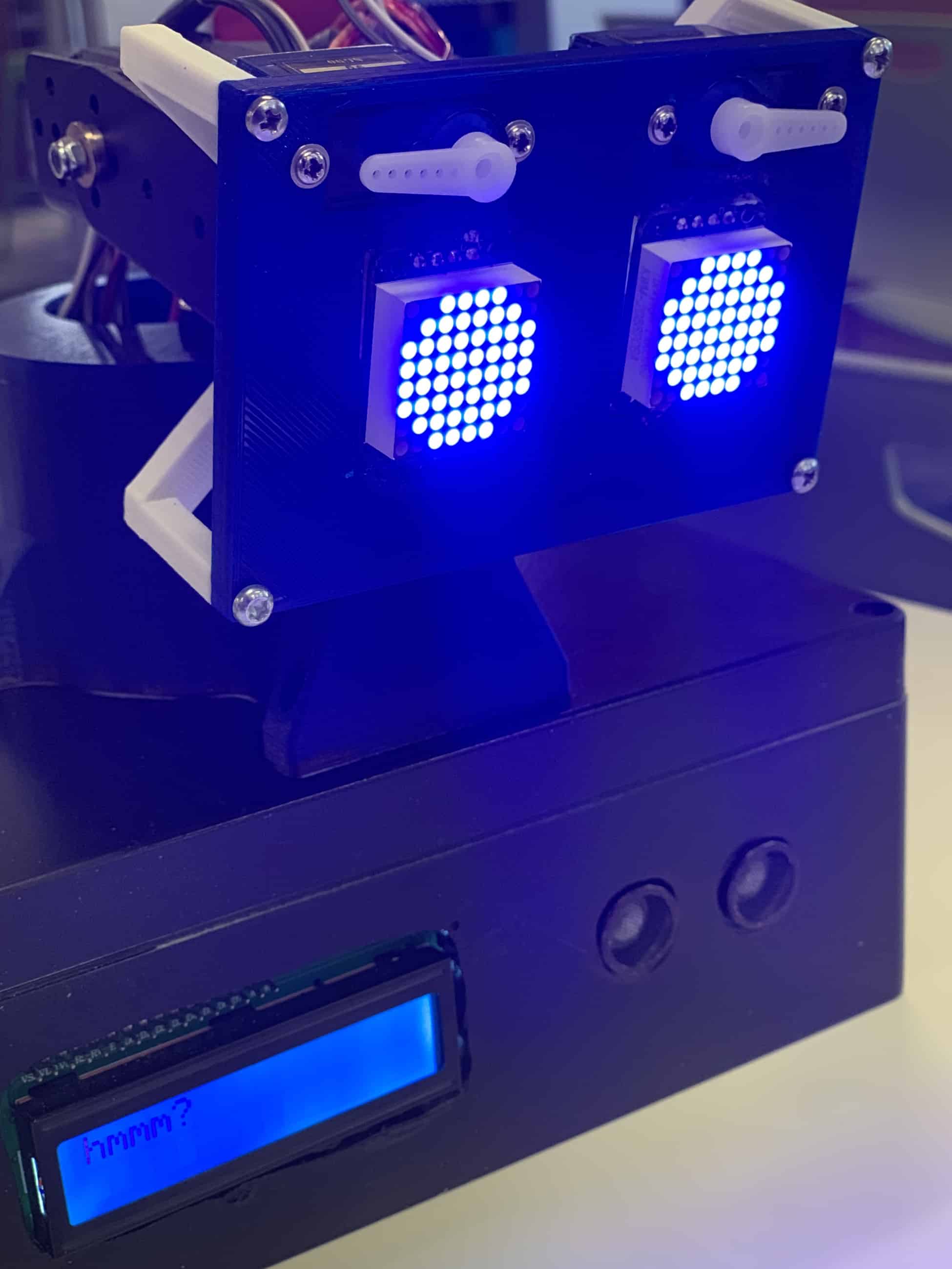
My main project is a robot that has the ability to display emotions. The first step I took to build this robot was to test each component of my robot individually and to wire all of the components together.
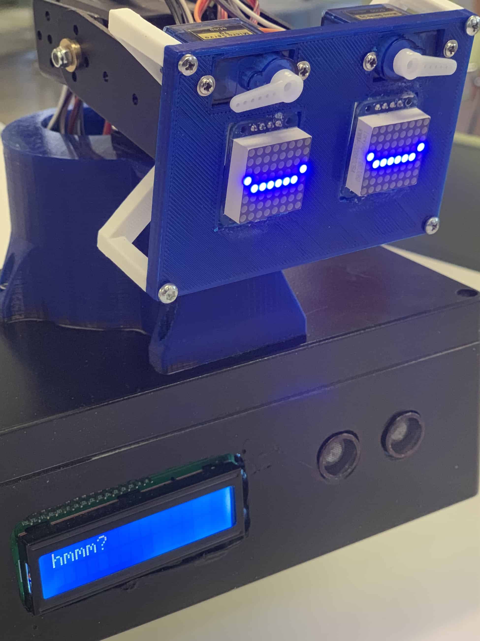
I chose to begin by testing each component individually because it ensures that each part functions properly before incorporating them to make a robot. I first started out by doing the blink test on the Arduino and testing the two LEDs that acts as eyes in my robot using the examples provided in the Arduino application. I modified the bitmaps in the example using 1’s and 0’s in order to create the expressions for the robot.
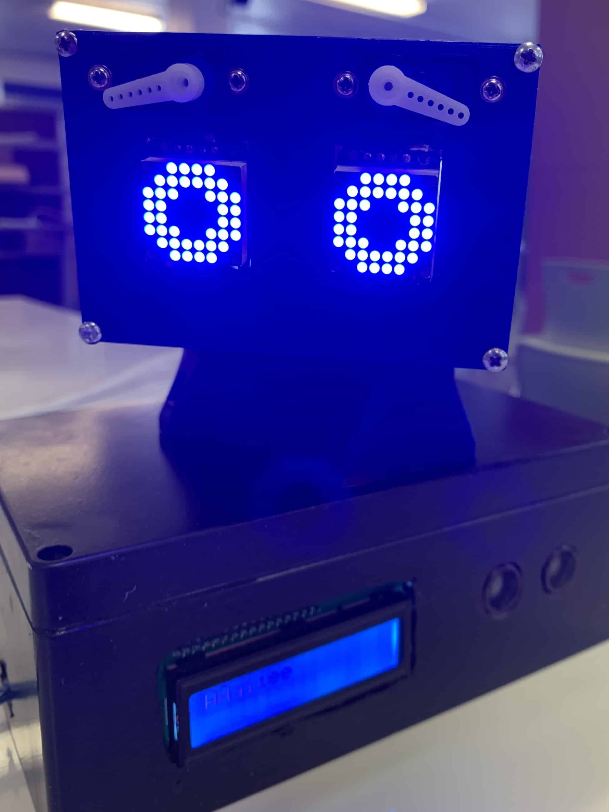
Next, I tested the ultrasonic sensor using an example I found online. An ultrasonic sensor works by outputting sound and bouncing back to the module. The distance is determined based on the speed and time it took to travel and bounce back from the object. I was able to combine the code for the LEDs and sensor early on so that when an object is at a distance closer than 5 cm, the expression on the LEDS changes from its normal blinking state to a shocked state in the shape of a ring.
Then, I assembled my wave shield, which is a part required for the Arduino Uno to produce sound. It produces sound off the files of an SD card in the form of mono WAV files through a speaker or the audio jack. I had difficulty during this step because I accidentally soldered 2 of 3 IC chips in the wrong orientation, so I had to wait for new parts to arrive before I could actually finish testing this part.
Lastly, I assembled the pan/tilt mount with standard sized hobby servos, which act as the neck of the robot. There are also 2 micro servos that act as eyebrows. These two were easily tested with the same example provided by the Arduino application.
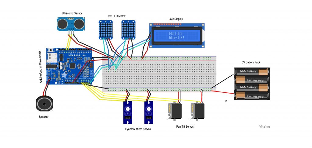
Finally, I wired all of these parts together so that I could run the code for each component without having to rewire. The wires are all connected through a breadboard, so that I can change the wires conveniently. All of the components are powered through the 5V port on the Arduino except the servos, which are powered by 6V batteries due to the excessive amount of voltage it takes to power them.
Project Schematic
Starter Project
My starter project is the Light Organ. When the light organ picks up sound, it displays a colorful LED display. This project taught me about the different components that make up the project and how to solder.
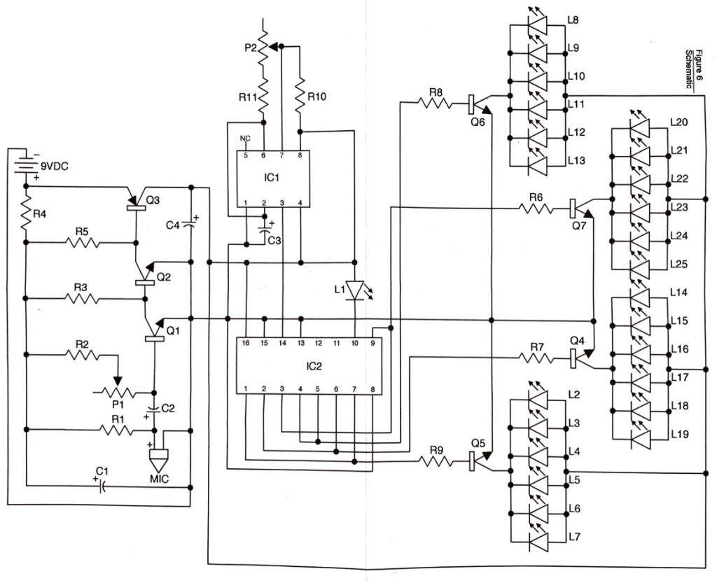
HOW IT WORKS
The light organ lights up whenever sound is picked up by the microphone. This whole project is powered by a 9V battery through the battery snap. The current goes through the resistors so that the current can be reduced and controlled. As sound is picked up, it is stored in the capacitors. The capacitors and resistors work together to filter out the low frequencies from the high frequencies. The transistor amplifiers amplify the high frequencies so that there is enough power to run the sequencing display circuitry made up of 2 IC chips. The IC1 chip digitizes the frequency and sends a clock pulse to the IC2 chip, which then acts as a counter and sends an output pulse to one of the 4 output transmitters. Each output transmitter controls a group of 6 LEDs. The sensitivity and speed of the light organ can be controlled by adjusting the trimmer transistors P1 and P2.


