Hand Gesture Controlled RC Car
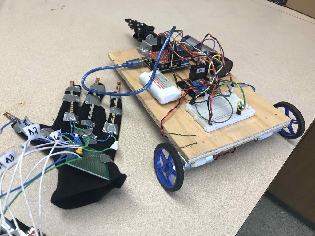
My main project is a Gesture Controlled RC Car, with a robotic claw. The user’s glove communicates with the car, commanding its movements through the user’s gestures.
Engineer
Maya S.
Area of Interest
Computer Science, Electrical Engineering
School
Newport High School
Grade
Incoming Junior
Reflection
Bill of Materials
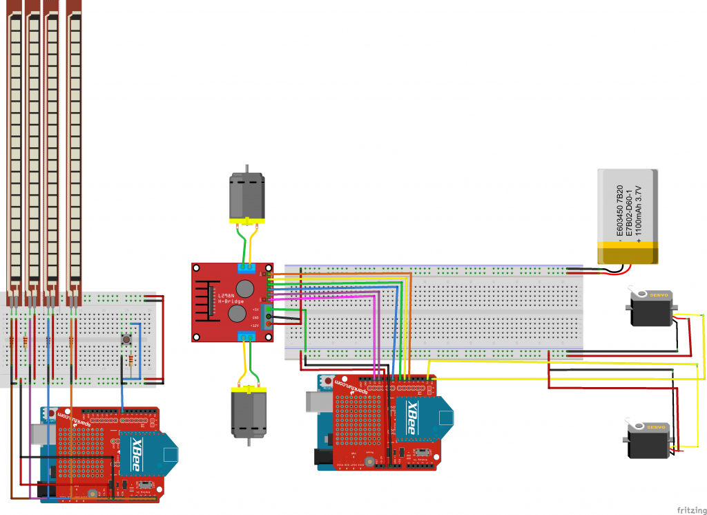
Build Plan
Final Milestone
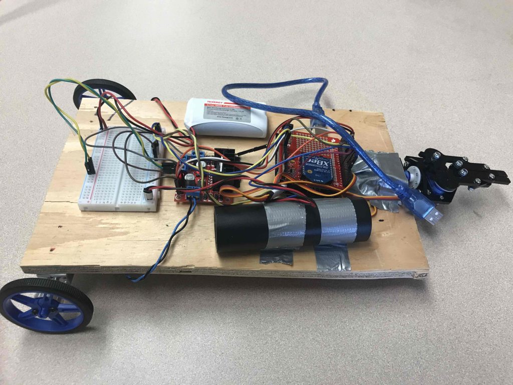
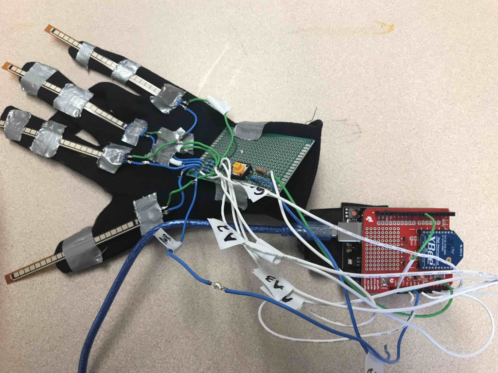
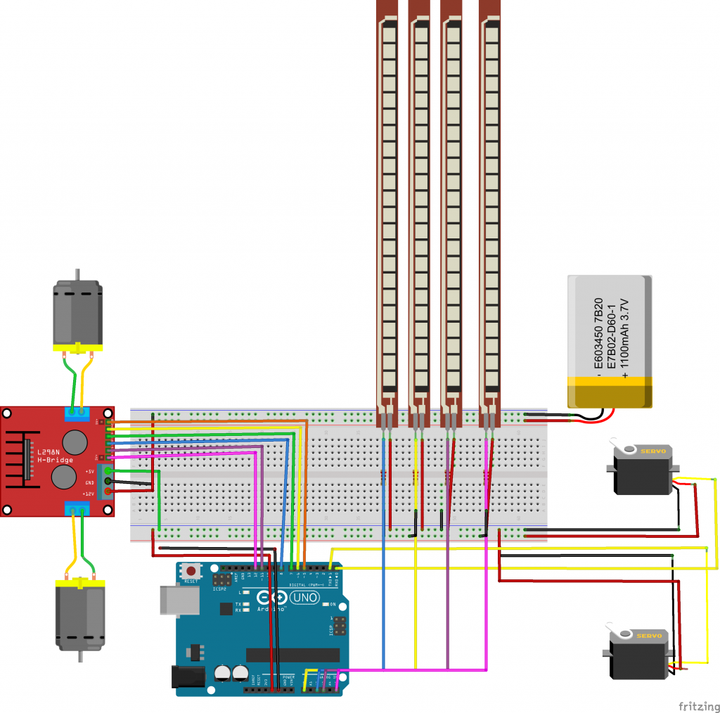
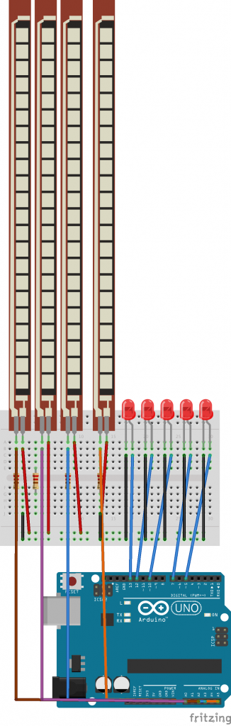
My final milestone was mounting my flex sensors onto a glove and my motors onto the RC Car. For the glove, I soldered all my connections for the flex sensors and the button onto a PCB. Each of the flex sensors are taped to the glove’s fingers, so that as the finger moves, the flex sensor bends. For the RC Car, I mounted all the components and motors onto wood. One of the largest challenges I faced during this milestone was working with the PCB on the glove. Because I had never soldered on a PCB before, it was difficult for me to make sure that the connections were solid. I ended up having to resolder and desolder my connections several times.
Third Milestone
Second Milestone
Code
First Milestone
Code
Starter Project
Picture
