MIDI Controller
A MIDI (Musical Instrument Digital Interference) controller is a device that generates electronic music through a series of hardware and software components. As the buttons are pressed, a signal is sent from the controller to a PC, where music software converts this signal into a distinct sound.
Engineer
Matthew F.
Area of Interest
Civil Engineering
School
Garden City High School
Grade
Rising Senior
Reflection
In my third year at BlueStamp, I learned about electrical engineering, coding, and music software in greater depth than I ever had before. My experience was extremely rewarding, as I acquired new knowledge and skills, and built a project that combines my unrelated interests. I am so glad to have been a part of the remote program, as I feel that experimenting on my own allowed me to learn even more than I ever had in previous years.
Final Milestone
For my final milestone, I was able to get my MIDI controller to make music! While I spent a lot of time building and wiring my project before now, I finally delved into the code. Luckily, I was able to find the code I needed for my project to work on the internet, and I downloaded it to my computer. This code allows my PC to interpret the signals sent by the Arduino when buttons on my controller are pressed. However, in order to get my project to actually make music, I needed to download two pieces of software, Hairless MIDI and Loop MIDI. Together, these programs convert the signal from Arduino to MIDI, the language that music software understands. I then proceeded to download Ableton, a popular program in the music industry. However, I could not seem to figure out how to use it properly. After hours and hours of troubleshooting, my MIDI controller still wasn’t making noise. I then realized that half of my wiring was incorrect, but even after fixing that, I had no luck. Finally, after trying many programs, I found FL Studio, which works very well! All of the buttons on my controller make different noises. In the future, I plan to connect the knobs and sliders to make my project even more advanced. However, my experience in building this project has been very positive and I am really excited to have a working MIDI controller!
Second Milestone
Completed Wiring
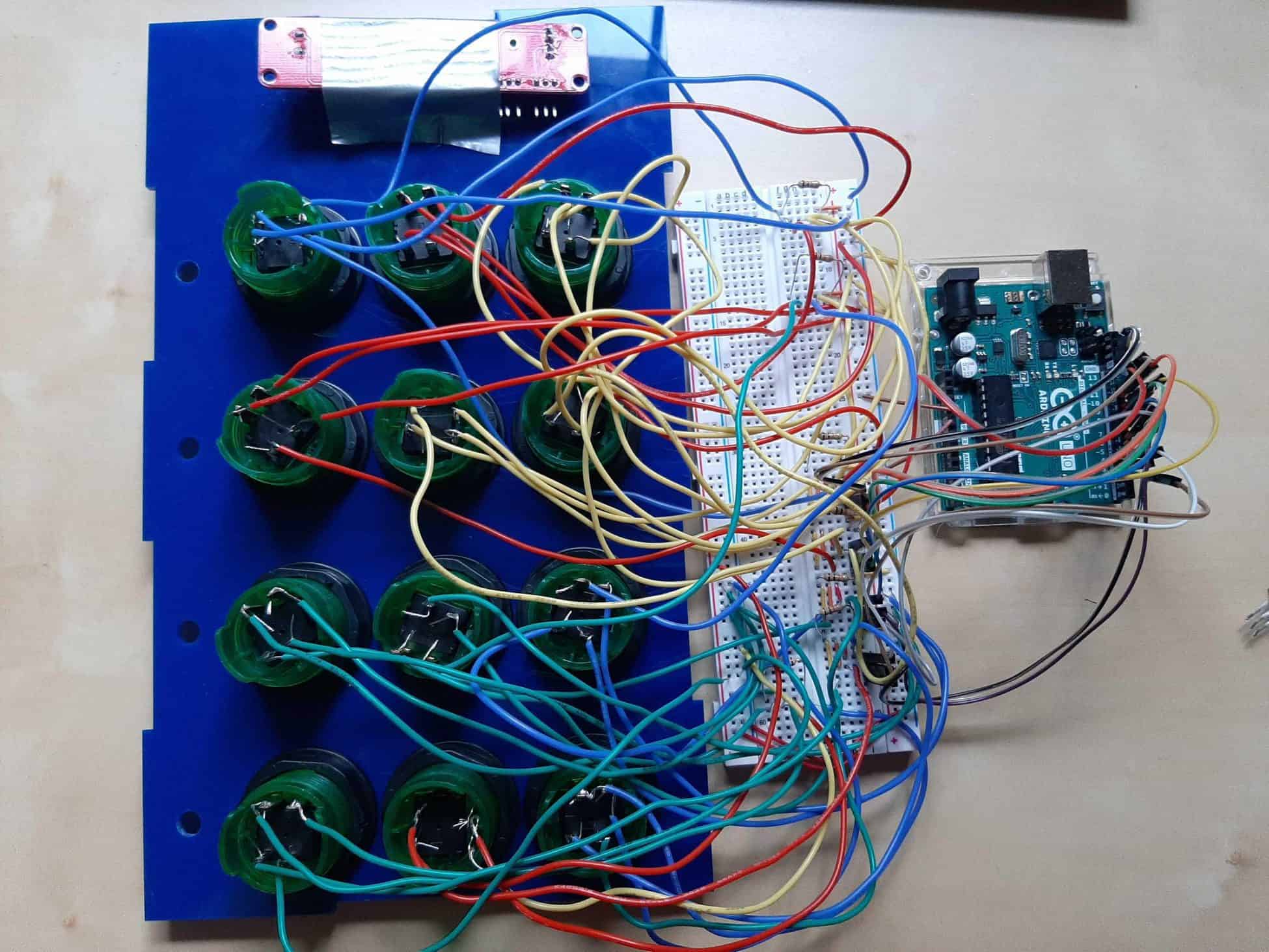
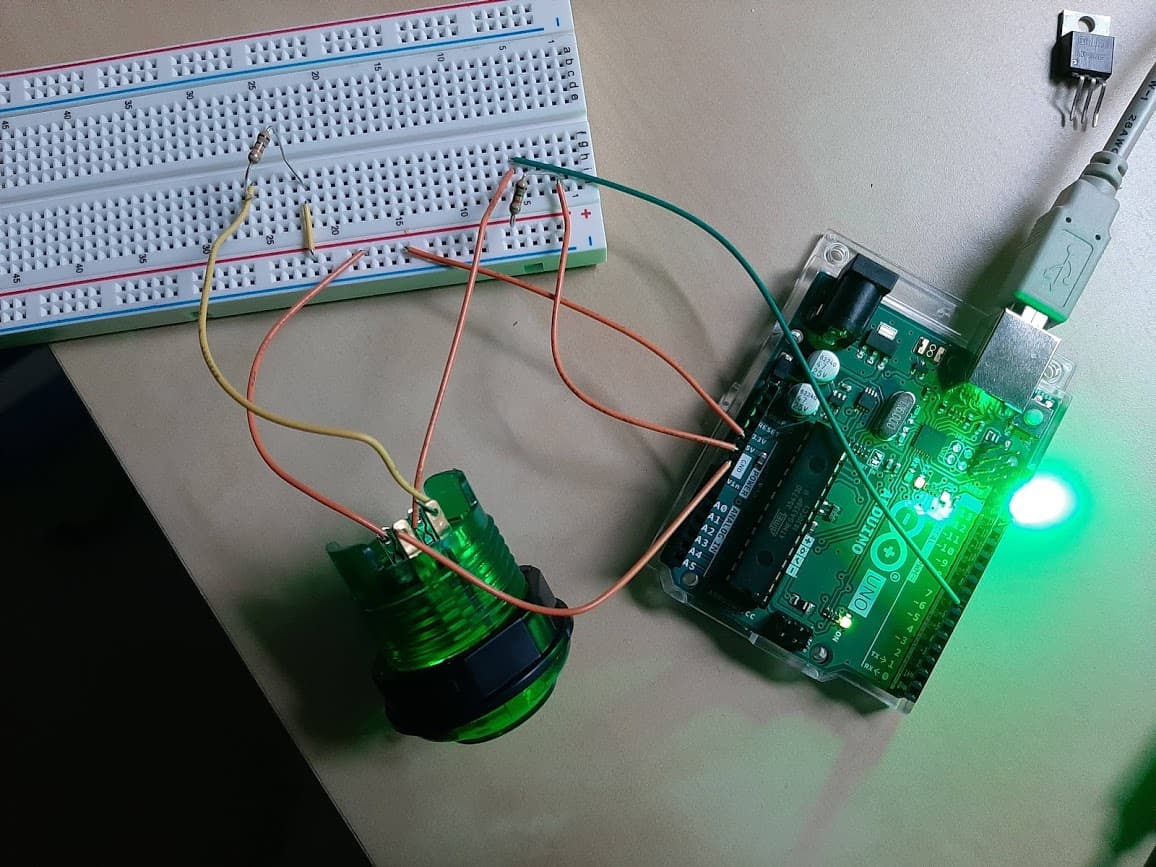
For my second milestone, I properly wired all of the buttons and a slider to the Arduino. To start, I soldered one wire to each of the four pins mentioned in my first milestone. After spending hours on soldering 48 wires, I then connected these wires to the breadboard. I first wired one LED pin on each button to the negative rail on the breadboard, which connected them all to ground on the Arduino. I then wired the other LED pin on each button to a pull-up resistor which was connected to the positive rail on the breadboard, thus connecting them all to 5V. Next, I wired the pins that control the button itself. I wired one pin on each to the positive breadboard rail which connects to 5V. The other pin was wired to both a digital pin so that the pressed button would be registered and a pull-down resistor which connects to ground through the negative rail. Alas, the twelve buttons were finally wired! I then connected a slider in a similar way. The slider had three pins. The first two connect to the negative rail (ground) and the positive rail (5V). The third pin connects to an analog pin on the Arduino since it is an analog input and has a wide range of input values. I am very glad to have completed the hardware aspect of this project and move onto learning how to get my MIDI controller playing music!
First Milestone