Wifi Controlled Mini Blimp
In the World of IoT (Internet of Things) my Wifi Controlled Blimp uses the ESP-8266 (a wifi module) to propel a helium-filled ballon in the desired direction. Designed with a custom PCB (Printed Circuit Board) and weight being a primary factor, this was no easy project.
Engineer
Matthew A
Area of Interest
Mechanical/ Aerospace Engineering
School
Fordham Leadership Academy
Grade
Incoming Senior
Final Milestone
Sophi's Code
For my final milestone with the Wifi Controlled Blimp, I uploaded Sophi Kravitz code on both the ESP-32 Huzzah Feather and ESP-8266. The first code, named ‘Blimpy_Server4’ was to be uploaded to the ESP-8266 (Blimp Module) and the ‘Blimpy_Client’ was to be uploaded to the Module in my controller. Before such, I needed to change a few things in the code such as the SSID and Password to the one of home router. I also needed to change the default gateway, router’s IP address, and the IP address that my ESP-8266 was emitting. An IP address is a set of numbers that are used to identify a device communicating over a network. This was all a success, the code uploaded with no errors!
Furthermore
However, I began to run into difficulty with wiring my Joystick and two buttons to the ESP-32. In order to solve this issue, I began to thoroughly scan the code Sophi created. This consisted of rereading her comments and researching the datasheet of the ESP-32. I was in search of a common thread between the input values in the code she gave and the pin values from the datasheet. Overall, I did find the common thread and was able to wire the joystick and on/off buttons accordingly. With such success in wiring the controls, I was able to change the variable inputs named ‘val3’, ‘val4’, ‘UpDown’, and ‘UpDown2’ which all go from 0 all the way to 4095. The variables ‘val3’ and ‘val4’ are in correspondence to the potentiometer values. A potentiometer is a varying resistor, as you begin to turn the knob the resistor will either increase or decrease in resistance, which in my case would vary from 0 to 4095.
In Conclusion
After doing this, I was able to wrap up my project with a little creativity in the enclosure. I utilized the Pringles can I ate out of that morning and was able to fit two breadboards, an ESP-32, and power-rails in order to add a compact aesthetic. In the end, everything turned out great!
Second Milestone
TB6552 Spec Sheets
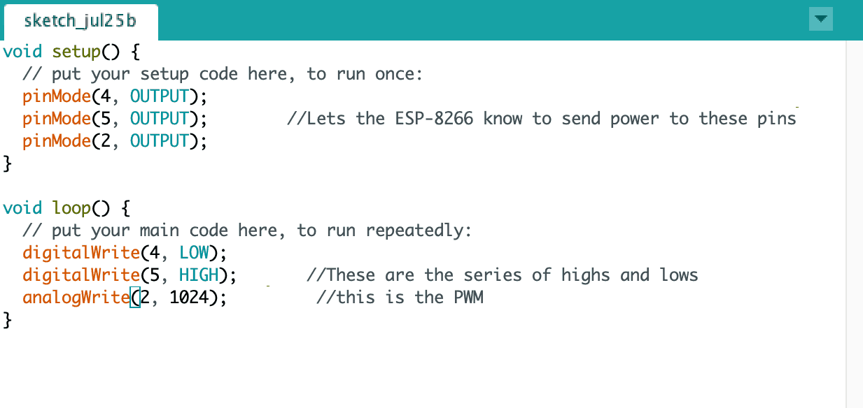
For my second milestone with the Wifi Controlled Blimp, I hard coded the ESP-8266 to spin the motors in any direction I desired. Based off the Eagle designs of my PCB, I figured out the Integrated Circuit responsible for making the motors turn: the motor driver TB6552FNG. After researching the motor driver’s datasheet, I came to the conclusion that the four input pins (IN1, IN2, PWM, and STBY) on control logic on the motor driver needed to be pulled in a series of highs and lows in order to get the desired rotation of either Clockwise and Counterclockwise. This series of highs and lows is made explicit in Figure 2. IN1 and IN2 are connected to the ESP-8266 by pins GPIO4 and GPIO5, and The PWM pin is linked to the GPIO2 pin. Specifically, the PWM (Pulse Width Modulation) input needs to be turned high in not a constant form but in a pulsing high-and-low for a specified duration. PWM is used for mimicking an analog output from a digital output source and is useful in my case for regulating the speed of my motors.
Furthermore
After doing some close following of my STBY (standby pin) input I realized it directly connected to the 3.3v power supply of the whole PCB. This means that whenever the board was turned on, the STBY input was always set to High unless the board stopped receiving power. This left me with little worry with coding how to set this input pin High or Low. With this, I ran my Arduino IDE and typed in a few DigitalWrite functions and AnalogWrite functions below.
ESP-8266 Motor Spin Code

In Conclusion
Something as simple as getting the motors turning on this ESP-8266 was quite a challenge due to the custom nature of the board. I learned how to properly and effectively use Integrated Circuit datasheets. In addition, I learned about the significance of Pulse Width Modulation. Without PWM, I would have my motors spins at full speed and possibly would’ve crashed my Blimp into a wall. After doing proper research on PWM in Arduino I found the analogWrite function very helpful in communicating with the motor driver. Using Eagle from Autodesk has been very helpful in understanding the wiring from the motor driver to the ESP-8266. Without such tools, I would not have been able to complete this milestone.
First Milestone
My First Milestone for the Wifi Controlled blimp was to program the ESP-8266. This consisted of soldering wires directly to the module, using a breadboard, and the Elegoo Uno R3 to create a Serial-to-USB link to my computer for programming. The ESP-8266 is the brain and heart of this project. To program the ESP-8266 was not straightforward. Based off a series of tutorial videos on YouTube, Forum Posts, Datasheets, and trial and error I figured out that I needed the Tx, Rx, VCC, GND, GPIO0, and RST (reset) pins in order to program the ESP-8266.
In Addition
The ESP-8266 was pre-soldered to the custom PCB and in order to get access to the programming pins, I soldered wires directly to it. What made programming so confusing was that each tutorial used different ESP-8266 models and wanted to use additional pins. In addition, the custom PCB was designed to program using a Tag Connect cable. A Tag Connect Cable can vary in size and pin number but its main purpose is to communicate data transmitted by serial and adapt it to Universal Serial Bus (USB) data so that the Arduino IDE can recognize it as a device. At the time I did not have a Tag connect cable so in the meantime waiting for it, I improvised and used the Elegoo Uno R3 as a Serial-to-USB. In order to do this I again looked up more information on YouTube with the guidance of a few mentors and was able to send an arduino example to make the ESP-8266’s built-in LED blink.
Eagle Files
In Conclusion
Overall, this milestone tested my patience and perseverance in learning about how Printed Circuit Boards (PCBs) work and doing proper research on the smallest components such as motor drivers or resistors. Throughout this milestone I made a series of mistakes such as shorting circuiting the board or giving the ESP-8266 5 volts of electricity instead of 3.3 volts. But the biggest mistake I made was not taking the module out of programming mode after uploading code to it from the Arduino IDE. If I did not figure out this mistake I would not have been able to test to see if the ESP-8266 was responding to the code.
Starter Project
My Starter Project is the Useless Machine, a highly addictive waste of someone’s time. When you flip the switch, an acrylic arm will come out and push it back to its original place. I enjoyed this project because I was able to learn the properties of various resistors, practice soldering terminal placements, switches, and screw tapping.
Demonstration
How it works
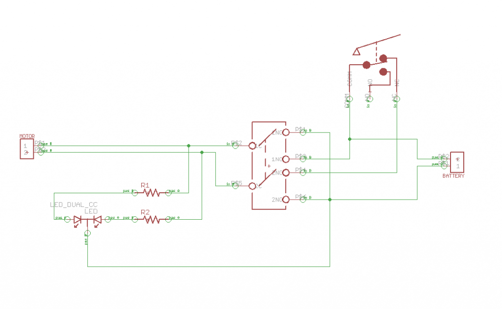
This machine works by me flipping a switch that activates a motor. This motor then responds by moving an acrylic arm to push the switch back in its initial position. What is not explicitly shown is that the switch is set in an either forward or reverse motion and is not an off switch. When the acrylic arm pushes the switch back to its initial position it sets the motor in reverse to later be stopped by a lever styled switch to stop the motor. The internals consisted of a custom Printed Circuit Board which holsters all the electrical components together and makes connections between them with embedded copper. In addition to the two resistors, two light emitting diodes, and other miscellaneous pieces such as velcro, and a battery holder.
The Experience
Aside from the external laser cut acrylic pieces, the assembly was relatively simple. I followed step-by-step instructions on where to solder these components to the PCB and its orientation and many other things. Most of the challenges of this project were in assembly. Merging the acrylic top and the side pieces was difficult because the protruding switch had kept the top piece from merging with the side pieces. I fixed this by removing washers and nuts pieces from the switch to have the top piece sit flush with the side pieces.


