Star Trek Tricorder
My main project at BlueStamp Engineering, a STEM summer camp for kids and teenagers in New York, is modeled after the Star Trek Tricorder. Basically, the Tricorder has multiple sensors whose data are interpreted by an Arduino Nano and sent/displayed to a TFT touchscreen. The user can interact with it to view current conditions to learn more about their environment.
Engineer
Mark C.
Area of Interest
Programming
School
Regis High School
Grade
Incoming Sophomore
Reflection
Before I went to BlueStamp Engineering camp, I had some robotics and general coding experience. However, I had little electrical engineering knowledge nor any idea on how to code an Arduino. I also knew little about what Arduinos did and nothing about breadboards. At BlueStamp Engineering, I first learned about soldering, which I also knew little about before. I then learned from experience and from my instructors how to get better at wiring sensors and coding an Arduino. Soon I got better at coding in the Arduino IDE and completing circuits between peripherals (such as sensors or the screen) and the Arduino Nano. Eventually, I also got more real-world experience with troubleshooting, debugging, and problem-solving. My student-defined sci-fi Star Trek Tricorder required a lot of wiring, coding, and problem-solving, which definitely expanded my view and experience/confidence/familiarity with working with similar parts/engineering/coding. I had a fun learning experience at BlueStamp and I will probably continue to utilize my skills in engineering and coding similar projects. Since I am only a rising sophomore, I am still not sure whether I will pursue electrical engineering, mechanical engineering, coding/computer science, or a similar field professionally in the future. I am certain whether I do electrical engineering or something similar, I will enjoy what I do. I will remember what I learned and experienced at BlueStamp Engineering about coding, engineering, and perseverance.
Final Milestone
Major Details:
My final milestone for the Star Trek Tricorder at BlueStamp Engineering camp was displaying more sensors’ data to the screen and wiring and testing a thermal camera to display to the screen (see Figures 1 through 4). The screen now will display data from the photocell and UV sensor and is color coded based on their readings. The screen will also display data from the GPS. I can also display the thermal camera to the screen (see Figure 4) by uploading a different code* (see Figure 6) to the Nano. The thermal camera and the UV sensor both require the same pins on the Arduino Nano (the SCL – clock – and SDA – data – pins), so I wired them to a CD4053BE multiplexer and wired the multiplexer to the Arduino. Multiplexers or muxes are devices that have multiple inputs connected and sends them into one output by switching between them according to how it is coded. To learn more about multiplexing in general, click here and click here for a tutorial for multiplexing with an Arduino (slightly different multiplexer, similar concept). This multiplexer is a triple two-channel multiplexer, meaning that it can have up to three sets of two inputs and wire each set into one output. For my purposes, I have it wired so that one sensor can be read at a time based on the value of a certain pin that I coded correspondingly to select the corresponding sensor.
About the code:
Similarly to the third milestone, the code (see Figure 5) will initialize with the same home screen that detects for whether the touchscreen was pressed and run a function corresponding to what was pressed. Additionally, the code will change the screen color based on the UV index for the UV sensor and brightness for the photocell. The thermal camera code (see Figure 6) will run the thermal camera and print colors to the screen based on the temperatures the camera detects. I coded the Nano to switch between reading the thermal camera and the UV sensor by writing:
pinMode(6,OUTPUT);
digitalWrite(6,value); //value can be LOW or HIGH - low for thermal camera, high for UV
Overcome Challenges:
- One problem I encountered was working with the multiplexer. When I was trying to switch between the two sensors, I would get a completely incorrect reading – sometimes it would read 0 and sometimes random numbers. I solved this by initially manually switching the mux select pin between positive and negative until I coded the Nano to do this for me, including right before the sensor is initialized.
- Another problem I encountered was that I wrote too much code. The Nano only has a limited amount of memory, so too much code would be problematic. This was highly problematic because I still decided to run this code despite the warning, “Low memory available, stability problems may occur” in the Arduino software compiler. “Stability problems” did occur – the program ran very slowly, strings (phrases that I programmed to print) were replaced with other strings, and eventually the Nano froze and would not accept any new code. I solved this by replacing the Nano and condensing the code before uploading it to the new Nano.
- A third problem I encountered was when I tested the thermal camera. When I adapted the example code to test the thermal camera with my screen (not the screen in their code), the screen refused to respond. Eventually I realized that when I changed the code for my screen, I forgot to add a line to initialize the screen, which fixed the problem.
*A note on the progress bar and what is next:
You may have noticed that some of the values (code and design) were not set to 100%. I planned on making a container 3D printed with the 3D files from the previous milestone to hold the Tricorder. However, because of time restraints, I could not complete this yet and I will do this or make a similar container later. I also planned on making the thermal camera accessible through the main code. Unfortunately, there is too little memory on the Nano to do this. Therefore, I will condense the code later to allow for room for more functionality, including the thermal camera.
Figures:
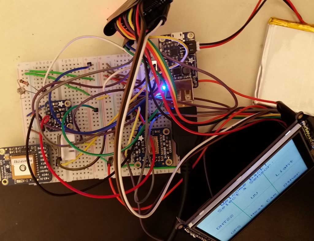
Figure 1: this shows the various sensors (including the new thermal camera), the Arduino Nano, and the screen powered by the battery.
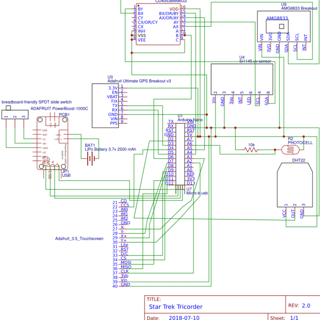
Figure 2: this is the new schematic of the Tricorder. This schematic now features the thermal camera and the UV sensor wired to the multiplexer, which is connected to the Nano.
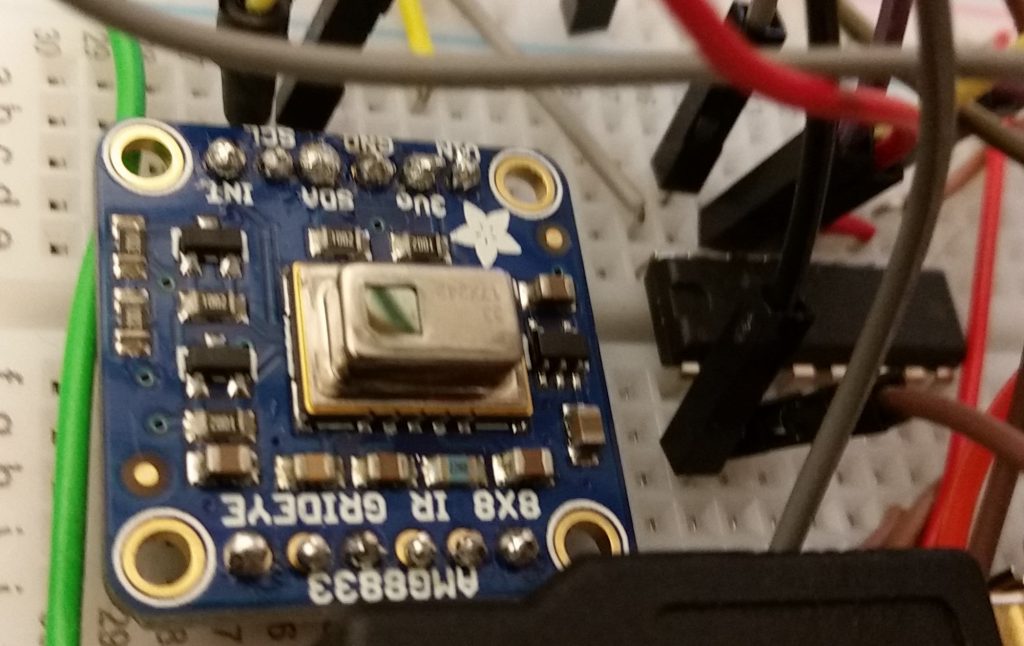
Figure 3: this shows the thermal camera (left) and the CD4053BE multiplexer (right).
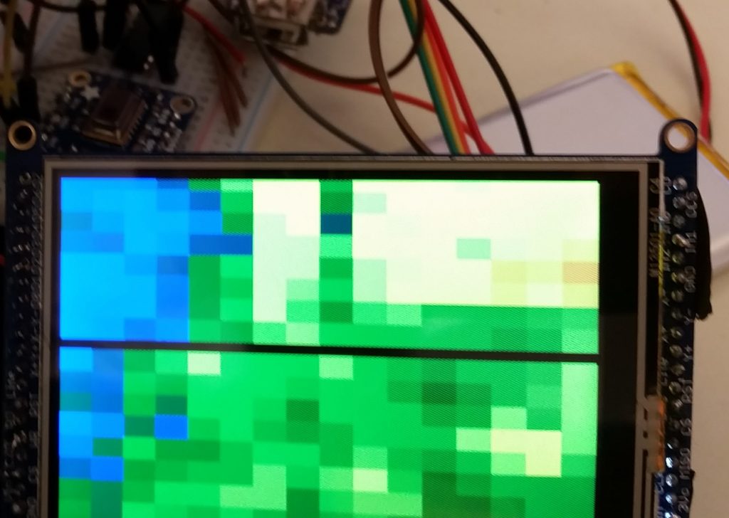
Figure 4: this is the thermal camera’s output displayed on the screen when my hand is held above the thermal camera.
//code written by Mark C at BlueStamp Engineering 2018
//milestone 3
//libraries for screen + touchscreen
#include "Adafruit_GFX.h"    // Core graphics library
#include "SPI.h"
#include "Adafruit_HX8357.h"
#include "TouchScreen.h"
//touchscreen
#define YP A2
#define XM A3
#define YM 7
#define XP 8
#define TS_MINX 110
#define TS_MINY 80
#define TS_MAXX 900
#define TS_MAXY 940
#define MINPRESSURE 2
#define MAXPRESSURE 1000
TouchScreen ts = TouchScreen(XP, YP, XM, YM, 300);
#define BOXSIZE_w 160//148
#define BOXSIZE_h 136
// The display uses hardware SPI, plus #9 & #10
#define TFT_RST -1  // dont use a reset pin, tie to arduino RST if you like
#define TFT_DC 9
#define TFT_CS 10
Adafruit_HX8357 tft = Adafruit_HX8357(TFT_CS, TFT_DC, TFT_RST);
//DHT library
#include "DHT.h"
#define DHTPIN 2     // what digital pin we're connected to
#define DHTTYPE DHT22   // DHT 22  (AM2302), AM2321
// Initialize DHT sensor.
DHT dht(DHTPIN, DHTTYPE);
//Define DHT variables; otherwise functions won't recognize them
float h=0;
float t=0;
float f=0;
float hic=0;
float hif=0;
//photocell
int photocellPin = 6;     // the cell and 10K pulldown are connected to a0
int photocellReading;     // the analog reading from the analog resistor divider
//UV sensor
#include "Wire.h"
#include "Adafruit_SI1145.h"
Adafruit_SI1145 uv = Adafruit_SI1145();
//define UV variables
float UVindex=0;
//set cursor, used to center text
unsigned long cursor1(int numb_right,int numb_up, int stringlength){
  //numb is number of rectangles, stringlength is length of text
  tft.setCursor(BOXSIZE_w *(numb_right-0.5) -(3*stringlength*3), BOXSIZE_h *numb_up);
//only works with default font, change (textsize*stringlength*3) for different text size (currently size is 3)
}
//defeault colors
#define txtcolor 0x001F //0x0FE9
#define bkgndcolor HX8357_WHITE
#define boxcolor 0xFE9
//bool definitions for later
bool dht_selected = false;
bool gps_selected = false;
bool uv_selected = false;
bool light_selected = false;
bool thermal_selected = false;
//GPS
#include "Adafruit_GPS.h"
#include "SoftwareSerial.h"
SoftwareSerial mySerial(3, 5);
Adafruit_GPS GPS(&mySerial);
#define GPSECHO  false //true debugs, false does not
boolean usingInterrupt = false;
void useInterrupt(boolean);
//run once at startup
void setup() {
//multiplexer cd4053b
pinMode(6, OUTPUT);
pinMode(A4, INPUT);
pinMode(A5, INPUT);
//GPS
GPS.begin(9600);
GPS.sendCommand(PMTK_SET_NMEA_OUTPUT_RMCGGA);
GPS.sendCommand(PMTK_SET_NMEA_UPDATE_1HZ);   // 1 Hz update rate
GPS.sendCommand(PGCMD_ANTENNA);
useInterrupt(true);
//UV
digitalWrite(6,HIGH);
uv.begin();
//Serial
Serial.begin(9600);
//DHT
dht.begin();
//screen + touchscreen
tft.begin(HX8357D);
//home screen load on startup
home1();
}
TSPoint p = ts.getPoint();
void loop(){
  //touchscreen
  //pressure detection (makes sure not too low)
  TSPoint p = ts.getPoint();
  if (p.z < MINPRESSURE || p.z > MAXPRESSURE) {
     return;
  }
  p.x = map(p.x, TS_MINX, TS_MAXX, 0, tft.width());
  p.y = map(p.y, TS_MINY, TS_MAXY, 0, tft.height());
  //note: graphics originate from top left corner, touch originates from bottom left corner
  //divided and multiplied numbers below to account for not registering touch correctly
  //detect for GPS pressed
  if ((p.y < (BOXSIZE_w /1.57)) && (p.x < (BOXSIZE_h*1.5))){
    gps_selected = true;
  }
  //Other bottom center
  else if ((p.y < ((BOXSIZE_w*2)/1.57)) && (p.x < (BOXSIZE_h*1.5))){
    thermal_selected = true;
  }
  else if ((p.y < ((BOXSIZE_w*3)/1.57)) && (p.x < (BOXSIZE_h*1.5))){
  }
  //DHT
  else if ((p.y < (BOXSIZE_w /1.57)) && (p.x < (2*BOXSIZE_h*1.5))){
    dht_selected = true;
  }
  else if((p.y < ((BOXSIZE_w *2) / 1.57)) && (p.x <(2*BOXSIZE_h*1.5))){
    uv_selected = true;
  }
  else if((p.y < ((BOXSIZE_w*3)/1.57)) && (p.x<(2*BOXSIZE_h*1.5))){      light_selected = true;      }    else {Serial.print("top");}    while (dht_selected == true){    dht_c(); }  while (gps_selected == true){    gps_c();  }   while (light_selected == true){   light_c();  }  while(uv_selected == true){    uv_c();   } /* while(thermal_selected == true){   tft.fillScreen(HX8357_WHITE);   tft.setCursor(1,1);   tft.println("For the thermal camera, please run 'thermal_camera_test_2_me'. Sorry for the inconvenience, have a nice day!");   delay(2000);   home1();  }*/ }  //GPS SIGNAL(TIMER0_COMPA_vect) {   char c = GPS.read();   // if you want to debug, this is a good time to do it! #ifdef UDR0   if (GPSECHO)     if (c) UDR0 = c;   #endif } void useInterrupt(boolean v) {   if (v) {     OCR0A = 0xAF;     TIMSK0 |= _BV(OCIE0A);     usingInterrupt = true;   } else {     // do not call the interrupt function COMPA anymore     TIMSK0 &= ~_BV(OCIE0A);     usingInterrupt = false;   } } uint32_t timer = millis(); unsigned long gpsbk = HX8357_GREEN; unsigned long gpstxt = HX8357_RED; void gps_c() {   tft.setCursor(2,2);   tft.setTextColor(gpstxt);   tft.fillScreen(gpsbk);   if (GPS.newNMEAreceived()) {     if (!GPS.parse(GPS.lastNMEA()))          return;   }   if (millis() - timer > 2000) {
  timer = millis();
  GPS.read();
  tft.print("Time:");
  tft.print(GPS.hour, DEC); tft.print(":");
  tft.print(GPS.minute, DEC); tft.print(':');
  tft.print(GPS.seconds, DEC); tft.print('.');
  tft.println(GPS.milliseconds);
  tft.print("Date: ");
  tft.print(GPS.month, DEC); tft.print('/');
  tft.print(GPS.day, DEC); tft.print("/20");
  tft.println(GPS.year, DEC);
  tft.print("Fix: "); tft.print((int)GPS.fix);
  tft.print(" quality: "); tft.println((int)GPS.fixquality);
  if (GPS.fix){
    tft.print("Location: ");
    tft.print(GPS.latitude, 4); tft.print(GPS.lat);
    tft.print(", ");
    tft.print(GPS.longitude, 4); tft.println(GPS.lon);
    tft.print("Location in degrees: ");
    tft.print(GPS.latitudeDegrees, 4);
    tft.print(", ");
    tft.println(GPS.longitudeDegrees, 4);
    tft.print("Speed (knots): "); tft.println(GPS.speed);
    tft.print("Angle: "); tft.println(GPS.angle);
    tft.print("Altitude: "); tft.println(GPS.altitude);
    tft.print("Satellites: "); tft.println((int)GPS.satellites);
  }
  else {
    tft.print("No GPS fix, sorry!");
  }
  delay(2000);
 }
}
//home screen
void home1(){
//bool used later for if something is selected
   dht_selected = false;
   gps_selected = false;
   uv_selected = false;
   light_selected = false;
   thermal_selected = false;
tft.fillScreen(bkgndcolor);
cursor1(2,0,13);
tft.setTextColor(txtcolor);
tft.setTextSize(3);
tft.setTextWrap(true);
tft.setRotation(1);
tft.print("Welcome back!\n");
tft.setCursor(BOXSIZE_w *(2-0.5) -(3*16*3),24);
tft.print("Select a Sensor:");
tft.drawRect(0, 48, BOXSIZE_w, BOXSIZE_h, boxcolor);
cursor1(1,1,5);
tft.print("DHT22");
tft.drawRect(BOXSIZE_w, 48,BOXSIZE_w, BOXSIZE_h, boxcolor);
cursor1(2,1,2);
tft.print("UV");
cursor1(3,1,5);
tft.print("Light");
tft.drawRect(BOXSIZE_w*2, 48,BOXSIZE_w, BOXSIZE_h, boxcolor);
cursor1(1,2,3);
tft.print("GPS");
tft.drawRect(0, 48+BOXSIZE_h,BOXSIZE_w, BOXSIZE_h, boxcolor);
cursor1(2,2,8);
tft.drawRect(BOXSIZE_w, 48+BOXSIZE_h,BOXSIZE_w, BOXSIZE_h, boxcolor);
tft.print("Heat Cam");
cursor1(3,2,5);
tft.drawRect(BOXSIZE_w*2, 48+BOXSIZE_h,BOXSIZE_w, BOXSIZE_h, boxcolor);
tft.print("Other");
}
//uv
unsigned long uvbkcolor = 0xFFE0;
unsigned long uvtxtcolor = HX8357_RED;
void uv_c(){
   digitalWrite(6,HIGH);   //high is uv, low is thermal camera
   //uv variables to fix error uv index = 0
   UVindex = uv.readUV();
   UVindex /=100.0;
   String UVadvice="";
   if (UVindex < 2){
    UVadvice="Low UV";
    uvbkcolor = 0x0400;
    uvtxtcolor = 0x07FF;
   }
   else if (UVindex < 5){
    UVadvice="Moderate UV";
    uvbkcolor = 0xEF40;
    uvtxtcolor = 0xF800;
   }
   else if (UVindex < 7){
    UVadvice="High UV";
    uvbkcolor = 0xFAA0;
    uvtxtcolor = 0x041F;
   }
   else if (UVindex < 10){     UVadvice="Very High UV";     uvbkcolor = 0xF800;     uvtxtcolor = 0xFDB6;    }    else if (UVindex > 10){
    UVadvice="Extremely High UV";
    uvbkcolor = 0x701C;
    uvtxtcolor = 0x0408;
   }
   tft.fillScreen(uvbkcolor);
   tft.setTextColor(uvtxtcolor);
   tft.setCursor(2,2);
   tft.print("Visible:");
   tft.println(uv.readVisible());
   tft.print("IR:");
   tft.println(uv.readIR());
   tft.print("UV index:");
   tft.println(UVindex);
   tft.print(UVadvice);
   delay(2000);
}
//photocell "light"
unsigned long lbkcolor = 0xFFE0;
unsigned long ltxtcolor = 0xF800;
void light_c(){
  photocellReading = analogRead(photocellPin);
  String light_reading = "";
  if (photocellReading < 10) {
    light_reading=" Dark";
    lbkcolor = HX8357_BLACK;
    ltxtcolor = HX8357_WHITE;
  } else if (photocellReading < 200) {
    light_reading=" Dim";
    lbkcolor = 0x8410;
    ltxtcolor = 0x69A0;
  } else if (photocellReading < 500) {
    light_reading=" Light";
    lbkcolor = 0xFFF0;
    ltxtcolor = 0xFC10;
  } else if (photocellReading < 800) {     light_reading=" Bright";     lbkcolor = 0xFFE0;     ltxtcolor = 0xF800;   } else {     light_reading=" Very bright";     lbkcolor = HX8357_WHITE;     ltxtcolor = HX8357_BLACK;   }    tft.fillScreen(lbkcolor);   tft.setTextColor(ltxtcolor);   tft.setCursor(2,2);   tft.print("Photocell says it is:");   tft.println(photocellReading);   tft.print("This is:");   tft.println(light_reading);   delay(2000); } //DHT  unsigned long dhtbkcolor = 0x07E0;  unsigned long dhttxtcolor = HX8357_BLACK;  void dht_c() {     h = dht.readHumidity();     // Read temperature as Fahrenheit (isFahrenheit = true)     f = dht.readTemperature(true);         hif = dht.computeHeatIndex(f, h);     //change color based on heat index     if (hif > 60 && hif <80) {      dhtbkcolor = 0xE643;      dhttxtcolor = 0x8420;     }     else if (hif > 80){
    dhtbkcolor = 0xFFE0;
    dhttxtcolor = 0xF800;
   }
   else if (hif < 60 && hif > 40) {
    dhtbkcolor = 0x07FF;
    dhttxtcolor = 0xFFFF;
   }
   else if (hif < 40 && hif >20){
    dhtbkcolor = 0x0019;
    dhttxtcolor = 0xFFF6;
   }
   else if (hif < 20){
    dhtbkcolor = 0x004B;
    dhttxtcolor = 0x9CF3;
   }
    tft.fillScreen(dhtbkcolor);
    tft.setTextColor(dhttxtcolor);
    // Compute heat index, temperature, humidity in Fahrenheit (the default)
    tft.setCursor(tft.width()/4.7,tft.height()/2-36);
    tft.print("Humidity: "); tft.print(h); tft.print("%\n");
    tft.setCursor(tft.width()/7.2,tft.height()/2-12);
    tft.print("Temperature: "); tft.print(f); tft.print("*F\n");
    tft.setCursor(tft.width()/6.2,tft.height()/2+12);
    tft.print("Heat index: "); tft.print(hif); tft.print("*F\n");
    delay(2000); //refresh screen with new data
}
#include "Adafruit_GFX.h"
#include "Adafruit_HX8357.h"
#include "SPI.h"
#include "Adafruit_SPITFT_Macros.h"
#include "Wire.h"
#include "Adafruit_AMG88xx.h"
#include "avr/pgmspace.h"
#define TFT_CS     10
#define TFT_RST    -1
#define TFT_DC     9
float pixels[AMG88xx_PIXEL_ARRAY_SIZE];
#define MINTEMP 22
#define MAXTEMP 34
#define optimize 0
#define interpolatemode 1
#define colorMode 1
#define spi_optimized_st77xx false
#if spi_optimized_st77xx == true
#define fillRectFast tft.fillRectFast
#else
#define fillRectFast tft.fillRect
#endif
#if colorMode == 1
const PROGMEM uint16_t camColors[] =
{0x0004,0x0004,0x0005,0x0005,0x0006,0x0007,0x0007,
0x0008,0x0008,0x0009,0x0009,0x000a,0x000b,0x000b,
0x000c,0x000c,0x000d,0x000d,0x000e,0x000f,0x000f,
0x0010,0x0010,0x0011,0x0012,0x0012,0x0013,0x0013,
0x0014,0x0014,0x0015,0x0016,0x0016,0x0017,0x0017,
0x0018,0x0018,0x0019,0x001a,0x001a,0x001b,0x001b,
0x001c,0x001c,0x001d,0x001e,0x001e,0x001f,0x001f,
0x001f,0x003e,0x003e,0x005d,0x005d,0x007c,0x009b,
0x009b,0x00ba,0x00ba,0x00d9,0x00d8,0x00f8,0x0117,
0x0117,0x0136,0x0136,0x0155,0x0174,0x0174,0x0193,
0x0193,0x01b2,0x01b2,0x01d1,0x01f0,0x01f0,0x020f,
0x020f,0x022e,0x024d,0x024d,0x026c,0x026c,0x028b,
0x028b,0x02aa,0x02c9,0x02c9,0x02e8,0x02e8,0x0307,
0x0307,0x0326,0x0345,0x0345,0x0364,0x0364,0x0383,
0x03a3,0x03a2,0x03c1,0x03c1,0x03e0,0x03e0,0x0400,
0x0c20,0x0c20,0x1440,0x1440,0x1c60,0x1c60,0x2480,
0x2ca0,0x2ca0,0x34c0,0x34c0,0x3ce0,0x44e0,0x4500,
0x4d20,0x4d20,0x5540,0x5540,0x5d60,0x6580,0x6580,
0x6da0,0x6da0,0x75c0,0x75c0,0x7de0,0x8600,0x8600,
0x8e20,0x8e20,0x9640,0x9640,0x9e60,0xa680,0xa680,
0xaea0,0xaea0,0xb6c0,0xbec0,0xbee0,0xc700,0xc700,
0xcf20,0xcf20,0xd740,0xdf40,0xdf60,0xe780,0xe780,
0xefa0,0xefa0,0xf7c0,0xffe0,0xffe0,0xffe0,0xffe0,
0xffc0,0xffc0,0xffa0,0xffa0,0xffa0,0xff80,0xff80,
0xff60,0xff60,0xff60,0xff40,0xff40,0xff20,0xff20,
0xff00,0xff00,0xff00,0xfee0,0xfee0,0xfec0,0xfec0,
0xfec0,0xfea0,0xfea0,0xfe80,0xfe80,0xfe80,0xfe60,
0xfe60,0xfe40,0xfe40,0xfe40,0xfe20,0xfe20,0xfe00,
0xfe00,0xfde0,0xfde0,0xfde0,0xfdc0,0xfdc0,0xfda0,
0xfda0,0xfda0,0xfd80,0xfd80,0xfd60,0xfd60,0xfd60,
0xfd40,0xfd40,0xfd20,0xfd20,0xfd00,0xfd00,0xfce0,
0xfcc0,0xfca0,0xfca0,0xfc80,0xfc60,0xfc40,0xfc40,
0xfc20,0xfc00,0xfbe0,0xfbe0,0xfbc0,0xfba0,0xfb80,
0xfb80,0xfb60,0xfb40,0xfb20,0xfb20,0xfb00,0xfae0,
0xfac0,0xfac0,0xfaa0,0xfa80,0xfa60,0xfa60,0xfa40,
0xfa20,0xfa00,0xfa00,0xf9e0,0xf9c0,0xf9a0,0xf9a0,
0xf980,0xf960,0xf940,0xf940};
#endif
Adafruit_HX8357 tft = Adafruit_HX8357(TFT_CS,  TFT_DC, TFT_RST);

Adafruit_AMG88xx amg;
unsigned long delayTime;
void setup() {
 // Serial.begin(9600);
 Serial.begin(115200);
  tft.begin(HX8357D);
digitalWrite(6,LOW);
    Serial.println(F("AMG88xx thermal camera!"));

    tft.fillScreen(HX8357_BLACK);

#define    displayPixelWidth  tft.width() /8
#define    displayPixelHeight   tft.height() / 8

    //tft.setRotation(3);

    bool status;

    // default settings
    status = amg.begin();
    if (!status) {
        Serial.println(F("Could not find a valid AMG88xx sensor, check wiring!"));
        while (1);
    }

    Serial.println( F(" – Thermal Camera Test – "));

    delay(100); // let sensor boot up

}
#define speedUpCompression 8
uint8_t compressionnumber;
uint8_t compressionflux=50;
byte runagain=0;
void loop() {
digitalWrite(6,LOW);
amg.readPixels(pixels);
 byte i=0;
 byte j=0;
 byte k=0;
compressionnumber=0;
 runagain++;runagain=runagain&15;
 while(k<8 ){  switch(k){case 0: j=0; break;case 1: j=2; break;case 2: j=4; break;case 3: j=6; break;case 4: j=1; break;case 5: j=3; break;case 6: j=5; break;case 7: j=7; break;           } if (i>7){i=0;k++;}
   #if colorMode <2     int colorIndex = map(pixels[i+j*8], MINTEMP, MAXTEMP, 0, 255);      #else      int colorIndex = map(pixels[i+j*8], MINTEMP, MAXTEMP, 0, 1023);     #endif #if interpolatemode == 0     tft.fillRect(displayPixelWidth *j, displayPixelHeight * i,displayPixelWidth, displayPixelHeight,(uint16_t)pgm_read_word_near(camColors+colorIndex)); #endif #if interpolatemode > 0
int pixelSizeDivide= 2*interpolatemode ;
int interpolatesampledir2=1; if(i<4){interpolatesampledir2=1;}else{interpolatesampledir2=-1;}//top(1) or bottom quadrunt (-1)
int interpolateSampleDir =1;// left  (1) or right quadrunt (-1)
int offset=0;
if (j<4){interpolateSampleDir =1;}
         else{interpolateSampleDir =-1;offset=displayPixelHeight-displayPixelHeight/pixelSizeDivide;}
for (int raster_x=0;raster_x !=(pixelSizeDivide*interpolateSampleDir)  ;raster_x += 1*interpolateSampleDir){
    for (int raster_y=0;raster_y != (pixelSizeDivide* interpolateSampleDir) ;raster_y += 1* interpolateSampleDir){
#if colorMode <2
int  tempcolor= map(pixels[(i+(interpolatesampledir2+raster_y/(pixelSizeDivide/2)))+(j+(raster_x/(pixelSizeDivide/2)))*8], MINTEMP, MAXTEMP, 0, 255);
#else
int  tempcolor= map(pixels[(i+(interpolatesampledir2+raster_y/(pixelSizeDivide/2)))+(j+(raster_x/(pixelSizeDivide/2)))*8], MINTEMP, MAXTEMP, 0, 1023);
#endif
tempcolor=(( tempcolor*(pixelSizeDivide-raster_y)+ colorIndex*raster_y)/pixelSizeDivide+(tempcolor*(raster_x)+colorIndex*(pixelSizeDivide-raster_x))/pixelSizeDivide)/2;
#if colorMode < 2 tempcolor=constrain(tempcolor,0,255);//subsample with real pixel and surounding pixels #else tempcolor=constrain(tempcolor,0,1023);//subsample with real pixel and surounding pixels #endif fillRectFast(displayPixelWidth *j +offset+ (interpolateSampleDir*displayPixelWidth/pixelSizeDivide)*(raster_x*interpolateSampleDir), displayPixelHeight* i+offset+(interpolateSampleDir*displayPixelHeight/pixelSizeDivide)*(raster_y*interpolateSampleDir), displayPixelWidth/pixelSizeDivide,displayPixelHeight/pixelSizeDivide, (uint16_t)pgm_read_word_near(camColors+tempcolor));   } }    #endif #if optimize >0
}
#endif
#if optimize >1
    }
#endif
 #if optimise > 1
 #endif

      i++;
  }
 if (compressionnumber>speedUpCompression){if (compressionflux<255) {compressionflux+=1;};  } else{   if (compressionflux>0){compressionflux-=1;};
 }
}
Third Milestone
Major Details:
My third milestone for the Star Trek Tricorder at BlueStamp Engineering camp was coding a touchscreen interface that displays temperature/humidity data when pressed (see Figures 1, 3, and 4), 3D CADing (computer-aided designing) a body to hold everything (see 3D models below), and attaching to the screen and testing a microSD card (see Figure 2). The 3D CAD files will be 3D printed and assembled by the Final Milestone. All parts will be placed within the 3D printed objects.The sensors will be able to work correctly with doors that will be able to open and close. The CAD files were mainly from https://www.thingiverse.com/thing:1701113 , but I did modify them, especially for size, using Blender.
About the code:
This code will display a white screen with green boxes and blue text that is centered (see Figure 4). Since there is no default way to center text, I created a function that takes in its location relative to the boxes and the length of the text to center the text:
unsigned long cursor1(int numb_right,int numb_up, int stringlength){
//numb is number of rectangles, stringlength is length of text
tft.setCursor(BOXSIZE_w *(numb_right-0.5) -(3*stringlength*3), BOXSIZE_h *numb_up);
//only works with default font, change (textsize*stringlength*3) for different text size (currently size is 3)
}
The code has the touchscreen detect for touch in any of the boxes. Here is an example for detecting for the box for the temperature/humidity (DHT) sensor:
else if ((p.y < (BOXSIZE_w /1.57)) && (p.x < (2*BOXSIZE_h*1.5))){ //p.x and p.y are coordinates for where is pressed
    Serial.print("DHT");
    dht_selected = true;
The boolean “dht_selected=true;” triggers this statement –
while (dht_selected == true){
  dht_c();
}
– running the function “dht_c();” which displays DHT sensor data on the screen with color changes based on the heat index. As of now, I only programmed the screen to display DHT data.
Overcome Challenges:
- One problem I overcame was drawing objects to the screen and then detecting touch from those coordinates. The problem was the graphics originated from the top left corner while touch originates from the bottom left corner. I accounted for this by changing the code accordingly.
- Another problem I encountered was when the code checked if a particular part of the screen was touched. The problem was wherever I pressed on the screen, it pulled up the DHT sensor (even when it was not hit).I solved this bug by changing while statements from
while (dht_selected = true){
  dht_c();
}
to
while (dht_selected == true){
  dht_c();
}
(changing “=” to “==” fixes this code).
Milestone Reflection:
Overall, this was an interesting and fun milestone to complete. I coded a lot for the interface of the touchscreen, which I enjoyed but still can continue progressing and modifying the code. Also, I had to deal a lot with numbers and calculations when I CADed, even though I did not start from scratch with CADing.
Figures:
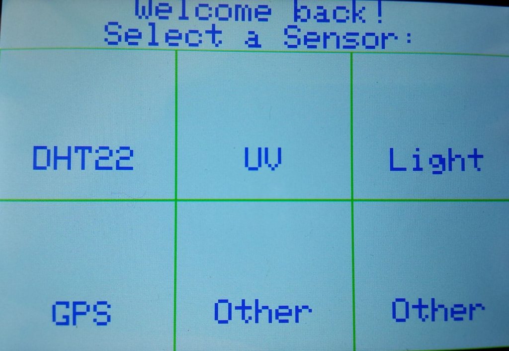
Figure 1: this is the screen with the new code
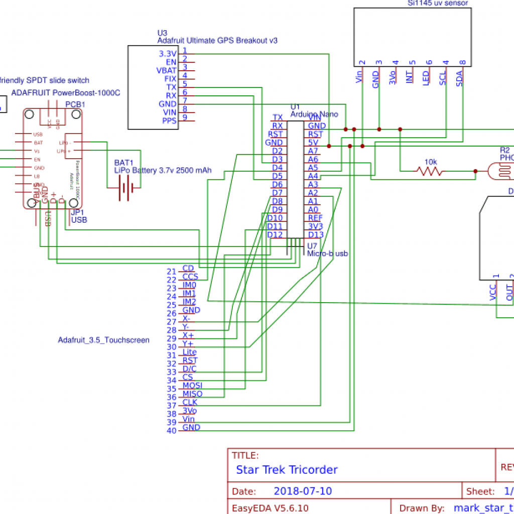
Figure 2: this is the updated schematics, updated for accessing the microSD card slot
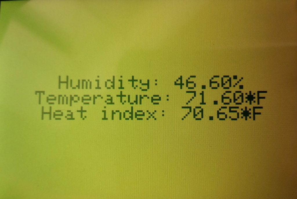
Figure 3: this is example data from the temperature/humidity sensor with the new code
//code written by Mark C at BlueStamp Engineering 2018
//milestone 3
//libraries for screen + touchscreen
#include "Adafruit_GFX.h"    // Core graphics library
#include "SPI.h"
#include "Adafruit_HX8357.h"
#include "TouchScreen.h"
//touchscreen
#define YP A2
#define XM A3
#define YM 7
#define XP 8
#define TS_MINX 110
#define TS_MINY 80
#define TS_MAXX 900
#define TS_MAXY 940
#define MINPRESSURE 2
#define MAXPRESSURE 1000
TouchScreen ts = TouchScreen(XP, YP, XM, YM, 300);
#define BOXSIZE_w 160//148
#define BOXSIZE_h 136
#define PENRADIUS 3 //is this necessary?
// The display uses hardware SPI, plus #9 & #10
#define TFT_RST -1  // dont use a reset pin, tie to arduino RST if you like
#define TFT_DC 9
#define TFT_CS 10
Adafruit_HX8357 tft = Adafruit_HX8357(TFT_CS, TFT_DC, TFT_RST);
//DHT library
#include "DHT.h"
#define DHTPIN 2     // what digital pin we're connected to
#define DHTTYPE DHT22   // DHT 22  (AM2302), AM2321
// Initialize DHT sensor.
DHT dht(DHTPIN, DHTTYPE);
//Define DHT variables; otherwise functions won't recognize them
float h=0;
float t=0;
float f=0;
float hic=0;
float hif=0;
//photocell
int photocellPin = 6;     // the cell and 10K pulldown are connected to a0
int photocellReading;     // the analog reading from the analog resistor divider
//UV sensor
#include "Wire.h"
#include "Adafruit_SI1145.h"
Adafruit_SI1145 uv = Adafruit_SI1145();
//define UV variables
float UVindex=0;
//set cursor, used to center text
unsigned long cursor1(int numb_right,int numb_up, int stringlength){
  //numb is number of rectangles, stringlength is length of text
  tft.setCursor(BOXSIZE_w *(numb_right-0.5) -(3*stringlength*3), BOXSIZE_h *numb_up);
//only works with default font, change (textsize*stringlength*3) for different text size (currently size is 3)
}
//defeault colors
#define txtcolor 0x001F //0x0FE9
#define bkgndcolor HX8357_WHITE
#define boxcolor 0xFE9
//bool definitions for later
bool dht_selected = false;
bool gps_selected = false;
bool uv_selected = false;
bool light_selected = false;
//run once
void setup() {
//UV
uv.begin();
//DHT
 Serial.begin(9600);
  dht.begin();
 //screen + touchscreen
 tft.begin(HX8357D);
 //home screen load on startup
 home1();
}
unsigned long home1(){
//bool used later for if something is selected
   dht_selected = false;
   gps_selected = false;
   uv_selected = false;
   light_selected = false;
tft.fillScreen(bkgndcolor);
cursor1(2,0,13);
tft.setTextColor(txtcolor);
tft.setTextSize(3);
tft.setTextWrap(true);
tft.setRotation(1);
tft.print("Welcome back!\n");
tft.setCursor(BOXSIZE_w *(2-0.5) -(3*16*3),24);
tft.print("Select a Sensor:");
tft.drawRect(0, 48, BOXSIZE_w, BOXSIZE_h, boxcolor);
cursor1(1,1,5);
tft.print("DHT22");
tft.drawRect(BOXSIZE_w, 48,BOXSIZE_w, BOXSIZE_h, boxcolor);
cursor1(2,1,2);
tft.print("UV");
cursor1(3,1,5);
tft.print("Light");
tft.drawRect(BOXSIZE_w*2, 48,BOXSIZE_w, BOXSIZE_h, boxcolor);
cursor1(1,2,3);
tft.print("GPS");
tft.drawRect(0, 48+BOXSIZE_h,BOXSIZE_w, BOXSIZE_h, boxcolor);
cursor1(2,2,5);
tft.drawRect(BOXSIZE_w, 48+BOXSIZE_h,BOXSIZE_w, BOXSIZE_h, boxcolor);
tft.print("Other");
cursor1(3,2,5);
tft.drawRect(BOXSIZE_w*2, 48+BOXSIZE_h,BOXSIZE_w, BOXSIZE_h, boxcolor);
tft.print("Other");
}
void loop(){
  TSPoint p = ts.getPoint();
  //touchscreen
  //pressure detection (makes sure not too low)
  if (p.z < MINPRESSURE || p.z > MAXPRESSURE) {
     return;
  }
  Serial.print("X = "); Serial.print(p.x);
  Serial.print("\tY = "); Serial.print(p.y);
  Serial.print("\tPressure = "); Serial.println(p.z);
  p.x = map(p.x, TS_MINX, TS_MAXX, 0, tft.width());
  p.y = map(p.y, TS_MINY, TS_MAXY, 0, tft.height());
  //note: graphics originate from top left corner, touch originates from bottom left corner
  //divided and multiplied numbers below to account for not registering touch correctly
  //detect for GPS pressed
  if ((p.y < (BOXSIZE_w /1.57)) && (p.x < (BOXSIZE_h*1.5))){
    Serial.print("GPS!");
    gps_selected = true;
  }
  //Other bottom center
  else if ((p.y < ((BOXSIZE_w*2)/1.57)) && (p.x < (BOXSIZE_h*1.5))){
    Serial.print("Other middle");
  }
  else if ((p.y < ((BOXSIZE_w*3)/1.57)) && (p.x < (BOXSIZE_h*1.5))){
    Serial.print("Other corner");
  }
  //DHT
  else if ((p.y < (BOXSIZE_w /1.57)) && (p.x < (2*BOXSIZE_h*1.5))){
    Serial.print("DHT");
    dht_selected = true;
  }
  else if((p.y < ((BOXSIZE_w *2) / 1.57)) && (p.x <(2*BOXSIZE_h*1.5))){
    Serial.print("UV");
    uv_selected = true;
  }
  else if((p.y < ((BOXSIZE_w*3)/1.57)) && (p.x<(2*BOXSIZE_h*1.5))){
     Serial.print("Light");     light_selected = true;
  }
   else {Serial.print("Are you touching the top?/nBecause nothing was detected :(");}
 while (dht_selected == true){
   dht_c();
 }
 while (gps_selected == true){
 //not coded yet
 }
}
//DHT
unsigned long dhtbkcolor = 0x07E0;
unsigned long dhttxtcolor = HX8357_BLACK;
unsigned long dht_c() {
     tft.fillScreen(dhtbkcolor);
   tft.setTextColor(dhttxtcolor);
    h = dht.readHumidity();
   // Read temperature as Fahrenheit (isFahrenheit = true)
    f = dht.readTemperature(true);
   // Compute heat index, temperature, humidity in Fahrenheit (the default)
    hif = dht.computeHeatIndex(f, h);
    tft.setCursor(tft.width()/4.7,tft.height()/2-36);
    tft.print("Humidity: "); tft.print(h); tft.print("%\n");
    tft.setCursor(tft.width()/7.2,tft.height()/2-12);
    tft.print("Temperature: "); tft.print(f); tft.print("*F\n");
    tft.setCursor(tft.width()/6.2,tft.height()/2+12);
    tft.print("Heat index: "); tft.print(hif); tft.print("*F\n");
    //change color based on heat index
    if (hif > 60 && hif <80) {
     dhtbkcolor = 0xE643;
     dhttxtcolor = 0x8420;
    }
    else if (hif > 80){
    dhtbkcolor = 0xFFE0;
    dhttxtcolor = 0xF800;
   }
   else if (hif < 60 && hif > 40) {
    dhtbkcolor = 0x07FF;
    dhttxtcolor = 0xFFFF;
   }
   else if (hif < 40 && hif >20){
    dhtbkcolor = 0x0019;
    dhttxtcolor = 0xFFF6;
   }
   else if (hif < 20){
    dhtbkcolor = 0x004B;
    dhttxtcolor = 0x9CF3;
   }
   delay(2000); //refresh screen with new data
}
This is the back.
This is the bottom.
This is an outer side panel.
This is the front door pull tab.
This is the frame.
This is the hood.
This is the hood’s side plug.
This is the large front door.
This is the left side panel.
This is upper horizontal support.
This is another side panel.
This is the top vertical wall.
This is the small front panel.
This is the screen holder.
This is the right side panel.
This is the middle divider.
Second Milestone
Figures:
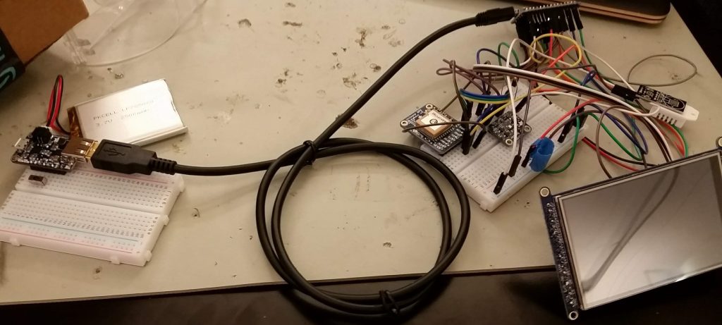
Figure 1: The Tricorder from milestone 1 wired up and powered by a battery can be seen above.
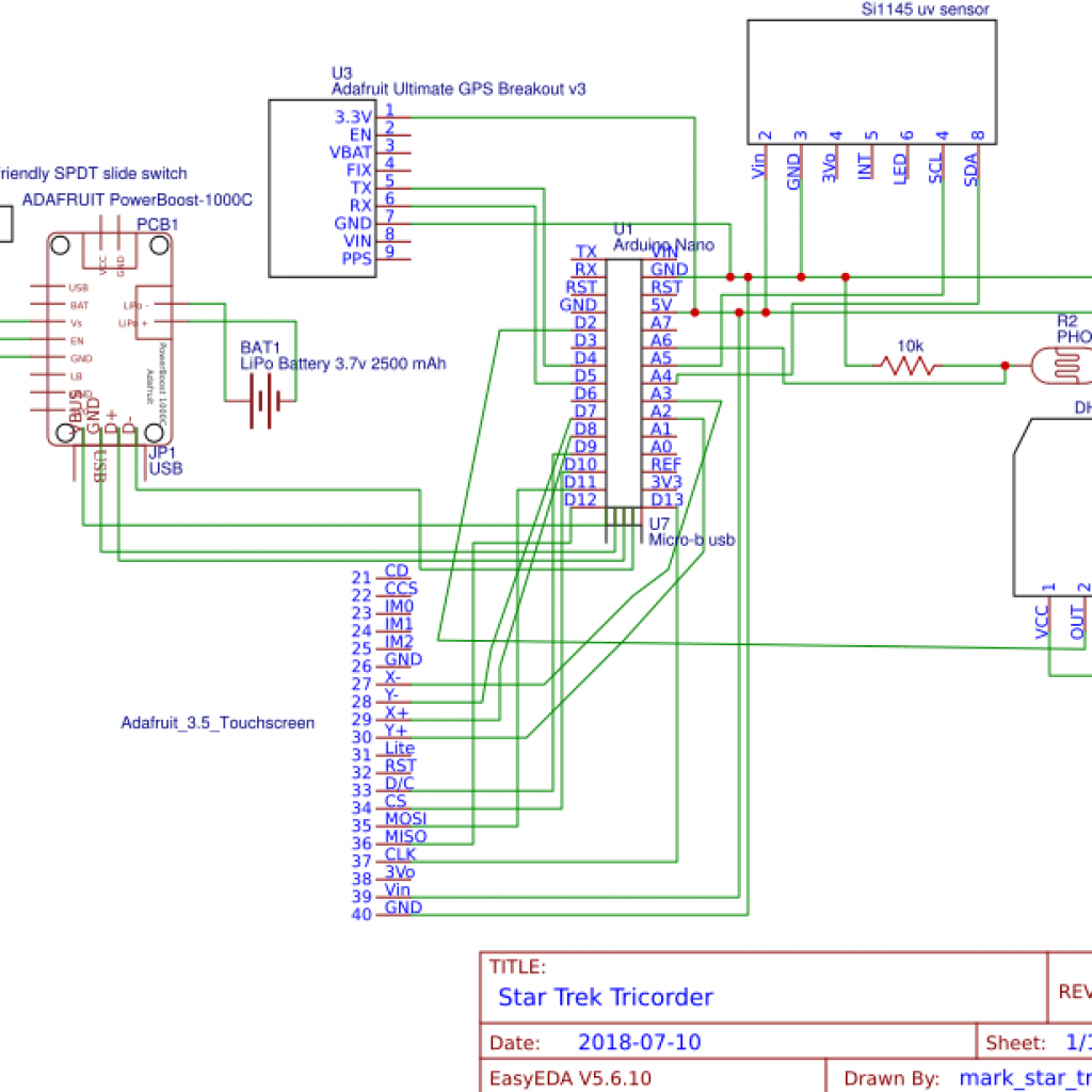
Figure 2: The updated schematics above now includes the PowerBoost 1000C and the LiPo battery.
For my second milestone for the Star Trek Tricorder at BlueStamp STEM coding and engineering camp, I attached a rechargeable LiPo battery to the Tricorder (see Figures 1 and 2) so that it can be powered without being connected to a computer. The lithium ion polymer battery (Adafruit 328; see Figure 3) can give an output between 3.7V and 4.2V. The battery has a maximum capacity of 2500 mAh for a total of ~10Wh. The battery has a 2-pin JST-PH connector that connects to the Adafruit PowerBoost 1000 Charger (see Figure 3). The PowerBoost accepts power from the battery and powers the Tricorder via a USB connected to the Arduino Nano. The PowerBoost can be turned on/off with a single-pole, double-throw (SPDT) slide switch (see Figure 3) via the PowerBoost’s enable (EN) pin. The switch will signal the EN pin to turn the PowerBoost on/off and therefore the switch will not have to carry any power. Since the switch has three pins, the other two can attach to VS (load shared output from the battery) and GND (ground). A separate micro USB port at the back of the PowerBoost can charge the battery and/or power the Tricorder.
I moved along very quickly with this milestone – I finished it within an hour or two. I discovered that it was very easy to make something, such as this project, powered by a battery. This milestone did not even require any coding – it was simply soldering header pins, attaching a slider switch, and connecting the PowerBoost via a USB to the Arduino Nano. This also shows how I have become more used to working with hardware and circuits in a timely manner.
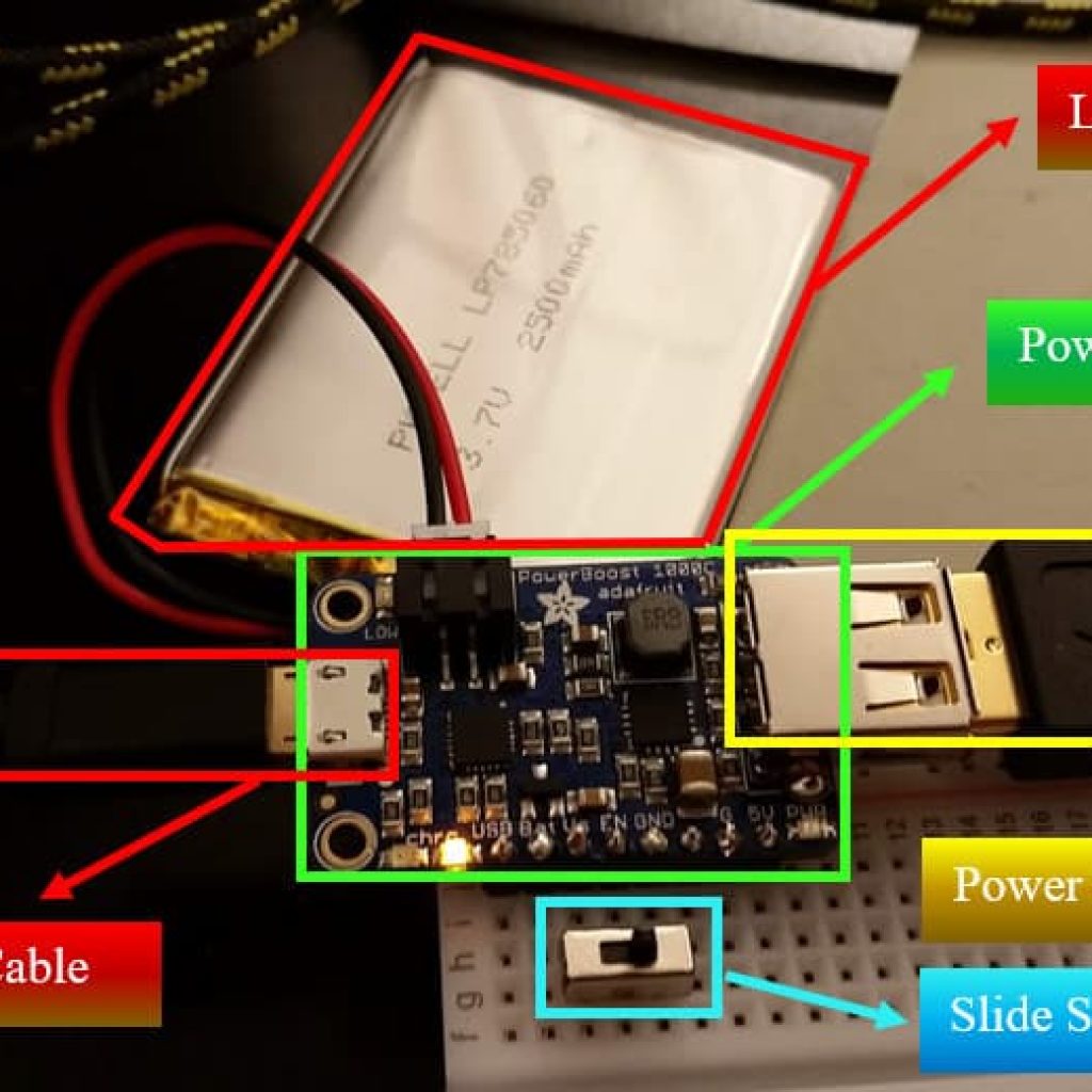
Figure 3: Above is the LiPo battery connected to the PowerBoost 1000C. The battery is currently charging, as indicated by the orange light on the bottom of the PowerBoost. The PowerBoost 1000C is attached to the Tricorder via a USB. The switch is set to the off position; therefore, the Tricorder is not receiving any power.
First Milestone
Figures:
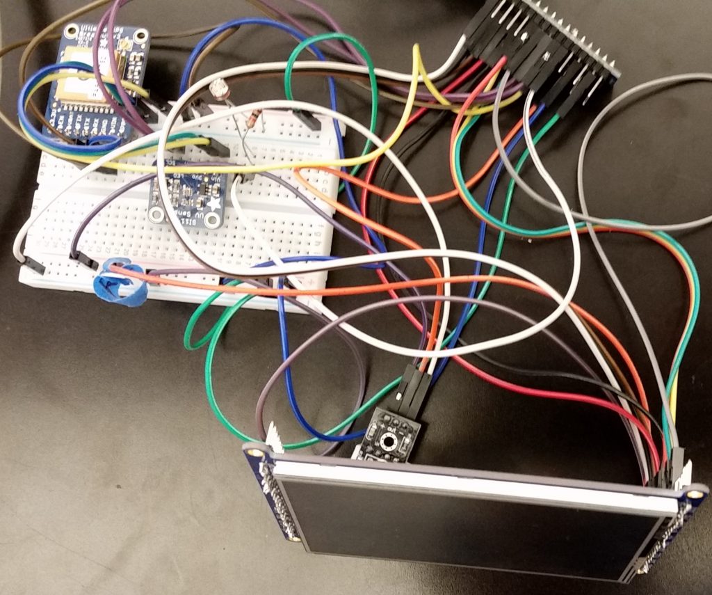
Figure 1: This picture shows my first milestone for the Star Trek Tricorder, including the TFT screen, UV sensor, temperature/humidity sensor, photocell, GPS, and Arduino Nano.
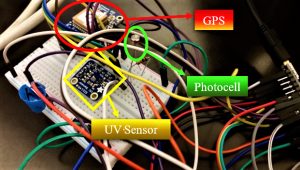
Figure 2: This picture shows a close-up of the UV and GPS sensors and the photocell.
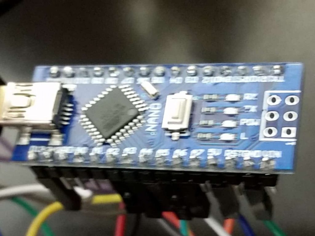
Figure 3: This picture shows a close-up of the Arduino Nano.
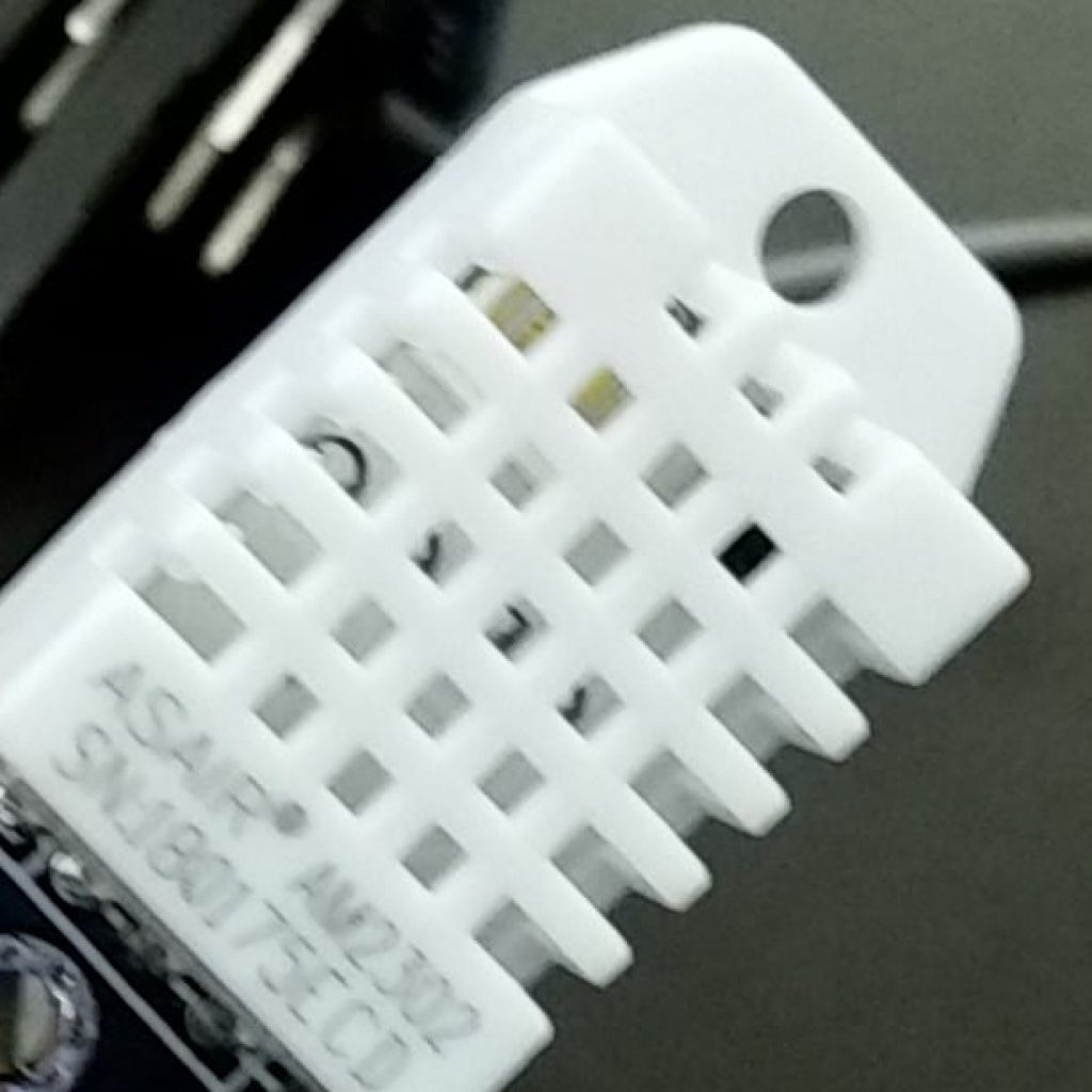
Figure 4: This picture shows a close-up of the DHT22 temperature/humidity sensor.
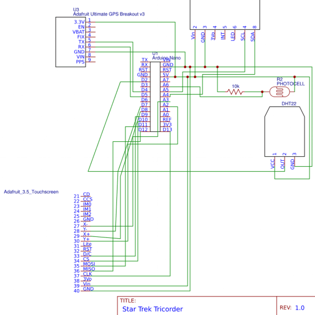
Figure 5: This is the schematics for the Star Trek Tricorder.
Major Details:
My main project at BlueStamp Engineering STEM summer camp is the Star Trek Tricorder, which features many sensors displaying data to a screen. For my first milestone, I connected GPS, UV, photocell, and temperature/humidity sensors to an Arduino Nano (see Figures 1 through 5). I programmed all sensor data except for the GPS to display to a TFT Screen. The Arduino Nano (see Figure 3) interprets data from the sensors and controls the screen by storing and executing code that I wrote. By default, many of these sensors transmit/receive data at the speed of 9600 baud, or 9600 bits per second, so I programmed the Nano accordingly. I prototyped the circuit on a breadboard. The Nano provides 5V of power to everything and accepts both power and data from a USB B mini cable. For the Nano, many of the sensors, and the screen, I had to solder header pins to them to make wiring/prototyping them with a breadboard easier. The Adafruit DHT22 (see Figure 4) is a digital temperature and humidity sensor that uses a capacitive humidity sensor and a thermistor. The capacitive humidity sensor detects and measures the conductivity of air, and the thermistor is a resistor that changes resistance based on temperature. The temperature sensor then sends out a digital, not analog, signal back to the Arduino Nano. Unfortunately, the temperature sensor only updates every two seconds with new data. The Adafruit photocell (see Figure 2), also called an LDR – Light-Dependent Resistor – or a photoresistor, is a resistor whose resistance varies based on the amount of light shining on it. The photocell’s data is sent back to the Nano via an analog pin. An analog pin can read the photocell’s infinite values, while if it were digital, only a certain range of values could be read. The Adafruit SI1145 UV Sensor uses visible and IR light from the sun to calculate the UV index. UV light, or ultraviolet light, is invisible to human eyes but affects people by allowing us to produce vitamin D. However, exposure to excessive amounts of UV light can lead to sunburn. The UV index is a measure of UV; a reading of 0-2 is low, 3-5 is moderate, 6-7 is high, 8-10 is very high, and 11+ is extremely high. This UV sensor uses the I2C communication protocol, also called the Inter-integrated Circuit Protocol, The I2C protocol allows a “master” chip to communicate with multiple “slave” chips. I2C is mainly intended only for short distance communication within one device and only requires two signal wires to exchange data/information. To utilize the I2C protocol, I connected the UV sensor’s SCL pin to the I2C clock master pin on the Nano (A5) and SDA to the I2C data master pin (A4). The SCL pin is the UV sensor’s I2C clock pin and is used to send signals at specific times. The UV sensor’s SDA pin is its I2C data pin. The Adafruit Ultimate GPS Breakout Version 3 (V3) tracks up to twenty-two satellites on sixty-six channels to determine its location. I connected the GPS’s TX pin to transmit data from the GPS to the Arduino Nano and RX to transmit data from the Arduino to the GPS. The Adafruit 3.5” TFT 320×480 + Touchscreen Breakout Board w/MicroSD socket (HXD8357D) is a color touchscreen LCD with a microSD socket and has two modes. The first mode is 8-bit mode, which is faster but requires more data pins with this screen. The other mode is SPI mode, which is slower but requires less pins for this screen and allows access to the microSD socket. I decided to use SPI mode to be able to access the microSD socket. I soldered the screen’s IM2 jumper closed to tell the screen to use SPI mode. Then I wired the touchscreen (see Figure 5).
About The Code
To read data/test each sensor, I mainly used the provided example code in the Arduino IDE provided by Adafruit (see Figure 6). To do this, I also had to download and install the provided libraries and import them into the Arduino IDE. However, for the main code that displays most sensor data to the screen, I combined and heavily edited example code, as seen in Figure 7 (currently collapsed).
Overcome Challenges:
- I encountered one problem when displaying new data, since printing this data to the screen will overlap with previous prints and will overlap. After several other failed attempts, I set the screen to fill with the background color and then print new data. The screen currently refreshes with new data every two seconds because the temperature sensor updates every two seconds and because otherwise it would be too fast for anyone to see.
- Another problem I ran into was how to display data from the sensor onto the screen. The problem I encountered was I referenced variables defined in one function in another function which the program would not recognize, so I defined the variables at the top of the code outside of any conflicting functions.
- I encountered a third problem when I tested the GPS. Unfortunately, it probably does work but I discovered that since I was testing indoors, the GPS couldn’t “fix” on any satellites. I’ll have to test it outdoors/somewhere else another time.
- A fourth problem I encountered was with the touchscreen functionality. When I ran the example code, it only said it was detecting touch near the bottom of the screen even when not being used. I eventually determined that the pins used for wiring it were important even if I changed it in the code correspondingly and therefore I had to rewire it to fix it. I therefore learned to follow the documentation correctly since each pin may have a specific and necessary function for something to work.
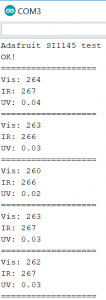
Figure 6: This is an example serial output of UV sensor data.
//code written by Mark C 2018
//milestone 1
//libraries for screen
#include // Core graphics library
#include
#include "Adafruit_HX8357.h"
// The display uses hardware SPI, plus #9 & #10
#define TFT_RST -1 // dont use a reset pin, tie to arduino RST if you like
#define TFT_DC 9
#define TFT_CS 10
Adafruit_HX8357 tft = Adafruit_HX8357(TFT_CS, TFT_DC, TFT_RST);
//DHT library
#include "DHT.h"
#define DHTPIN 2 // what digital pin we're connected to
#define DHTTYPE DHT22 // DHT 22 (AM2302), AM2321
// Initialize DHT sensor.
DHT dht(DHTPIN, DHTTYPE);
//Define DHT variables; otherwise functions won't recognize them
float h=0;
float t=0;
float f=0;
float hic=0;
float hif=0;
//photocell
int photocellPin = 6; // the cell and 10K pulldown are connected to a0
int photocellReading; // the analog reading from the analog resistor divider
//UV sensor
#include
#include "Adafruit_SI1145.h"
Adafruit_SI1145 uv = Adafruit_SI1145();
//define UV variables
float UVindex=0;
void setup() {
//UV
uv.begin();
//DHT
Serial.begin(9600);
dht.begin();
//screen
tft.begin(HX8357D);
tft.fillScreen(HX8357_RED);
}
void loop(){
//DHT
// delay(2000); delay accounted for in screen refresh
h = dht.readHumidity();
// Read temperature as Fahrenheit (isFahrenheit = true)
f = dht.readTemperature(true);
// Compute heat index in Fahrenheit (the default)
hif = dht.computeHeatIndex(f, h);
//Screen display data
testText();
//photocell
photocellReading = analogRead(photocellPin);
//UV
UVindex = uv.readUV(); //float done earlier; ALWAYS REMEMBER TO REMOVE FLOAT, define/float variable above if printing later
UVindex /= 100.0;
}
unsigned long testText() {
//SCREEN
tft.setCursor(2,2);
tft.setRotation(1);
tft.setTextSize(3);
tft.setTextColor(0x3E83);//RGB565 for color value ex: 0x632C is gray
tft.setTextWrap(true);
//DHT readings
tft.print("Temperature Sensor Value:\n");
tft.setTextColor(HX8357_BLUE);
tft.print("Humidity: ");
tft.print(h);
tft.print(" %\n");
tft.print("Temperature: ");
tft.print(f);
tft.print(" *F\n");
tft.print("Heat index: ");
tft.print(hif);
tft.print(" *F\n");
//photocell readings
tft.setTextColor(0x3E83);
tft.print("Photocell reading:\n");
tft.setTextColor(HX8357_BLUE);
tft.print(photocellReading); // the raw analog reading
tft.setTextColor(0x07FF);
if (photocellReading < 10) {
tft.println(" - Dark\n");
} else if (photocellReading < 200) {
tft.println(" - Dim\n");
} else if (photocellReading < 500) {
tft.println(" - Light\n");
} else if (photocellReading < 800) {
tft.println(" - Bright\n");
} else {
tft.println(" - Very bright\n");
}
//UV sensor readings
tft.setTextColor(0x3E83);
tft.print("UV sensor Readings:\n");
tft.setTextColor(HX8357_BLUE);
tft.print("\nVis: ");
tft.print(uv.readVisible());
tft.print("\nIR: ");
tft.print(uv.readIR());
tft.print("\nUV: ");
tft.print(UVindex);
//refresh screen after 2 seconds
delay(2000);
tft.fillScreen(HX8357_RED);
}