
Introduction Paragraph
My name is Malcolm, I’m a rising Junior at Denver School of Science and Technology: Cole High School, and I want to become an automotive engineer. For my six weeks at BlueStamp I chose to conduct two projects, the Larson Scanner Kit and Paul Bleisch’s RC Robot Tank. My starter project, the Larson scanner kit, I chose to conduct because it was originally part of a 1982 Pontiac Trans Am or, simply put, a car. I chose to conduct the remote controlled robot tank because of my love for cars. This also helped me to decide what specifically I wanted to do within automotive engineering. Both products are described and shown functioning below.

Documentation
Here is my Schematic

Here is my Bill of Materials
Here is my Code for the Tank
Reflection Paragraph
Throughout my six weeks, I learned a few very important lessons. The first lesson, being one of the most challenging to recover from, was that I placed half of the circuitboard backwards. The disadvantages were that I had to take all of the components off and either flip them or replace them. However, the advantages were that I learned from this, changed the problems, and will be remembered in the future. Even though this lesson had short term disadvantages, it had, has and will have long term benefits. Another lesson I learned is that coding can be hard if you don’t know what is wrong or how to fix it. Starting from scratch makes coding all the more frustrating. This helped me to understand that being stuck on something isn’t always a bad thing, it gives you something to work on, making coding entertaining. However, building was even more amusing. I knew that this portion would come to me more naturally, caused by my liking for hands on experiences. BlueStamp helped me to realize that there are multiple functions in one career, therefore giving me more options within automotive engineering to choose from.
Final Video
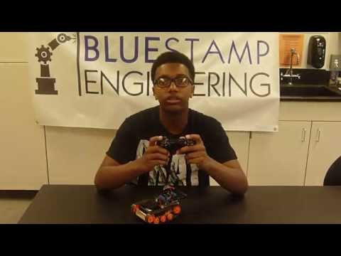
For this video, I was able to upload a code onto the Arduino that, similar to my last video, sensed buttons being pressed, sent a signal to the arduino, and created an output to certain pins in order to move a motor forward or backward instead of LEDs turning on or off. The L1, L2, R1, and R2 buttons control the motors, 1s going forward and 2s going backwards. However, this time the motor shield was mounted and I was controlling the motors. Some drawbacks that I came across were that the motor shield was different from the original. What I did to recover was find a new code for that motor shield specifically and fuse the PS2 controller code with it in order to control the motor shield correctly.
Milestone #2
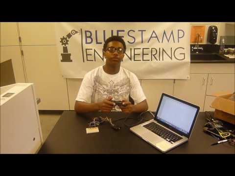
For this update, I was able to hook up some LEDs through a breadboard and control them with my PS2 controller wirelessly, using the L1, L2, R1, R2 buttons. I was not able to control the tank because of some electrical problems that I had, one being that my Motor Shield had a short circuit and fried. For this to happen, I was testing to see if there was enough current going through the Arduino and the motor shield. Too much voltage was applied to the motor shield and therefore fried. I had to adjust my standard in order to be the most effective and successful. The code that I uploaded to the Arduino made the LEDs light up if a button is pressed or turn off when a button is released.
Milestone #1
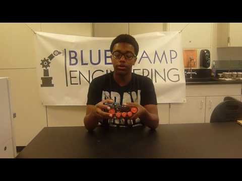
For this milestone, I was able to upload some code on my Arduino to power the motors in order to move the tank. This was not yet controlled by the PS2 controller. It had a self controlling code that made the tank move forward for three seconds and then stop for one second continuously. Some hurdles I had to overcome were the motor shield would control a motor both clockwise and counter-clockwise but the other motor would only spin clockwise. I conducted a series of tests in order to find the problem which was the motor shield itself. Here is the video, in which everything else is explained, shows how the tank works and explains my plan for my next milestone.
Starter Project
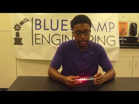
I chose the Larson Scanner Kit because it was something that appealed to me. I actually had to look up what I was going to be making. Once I figured out that the original piece was part of a car, I couldn’t help but choose the project. The way this project works is that the battery sends power to the circuitboard. The microchip is programmed so that the lights have the effect of swiping back and forth. The button on the side changed the speed. A problem I came across was having half of the components on the circuitboard flipped. As expected, I got a short circuit and had to get a new microchip. Here is a video of what it does and how it works.
Malcolm,
Thanks for sharing these videos. It is great that you are learning to design and implement electronic displays and robotics using microcontrollers! Good work!!
Best wishes for continued success!!
Ron Fontenot Sr.
Great job, Malcolm! Proud of you. Enjoy, explore and learn, learn, learn then teach! Luv ya
Nice job, great nephew! I didn’t understand a word you said, but you did an excellent job explaining it! I’m still trying to figure out how the telephone and light bulbs work! I do not have a scientific mind….as you can see ! Love ya!
You are doing an awesome job Malcolm and I am so very proud of you. Your presentations are clear and demonstrations are understandable. Continue to explore and learn. love, Grandy