Emotive Robot
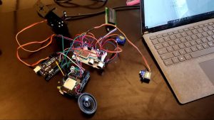
The Emotive robot is an Arduino-powered robot that can mimic emotion and react to human presence.
Engineer
Levi L
Area of Interest
Computer Science
School
Ramaz Upper School
Grade
Incoming Junior
Final Milestone
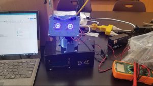
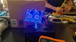
For my final milestone, I 3D printed the parts and assembled the robot together. I also coded the robot to seem to have “emotion” by making it look around the room. When something gets too close to it, it’s eyes widen, the eyebrows shoot up, and the head moves more frequently to give it a “nervous” look.
How it works
Completing this milestone was the longest part of this project. First, I had to download 3D files from a website for the structure of the robot. However, some of the dimensions were too big, so I had to resize it. This was a challenge since I never used 3D modelling software before, but I worked it out in the end and made sure everything fit. Printing was also tedious, since the parts took so long. But this was also a good thing, since I was able to progressively build the robot instead of doing it all at once. I had to make holes on the face of the box for the different components. This exposed me to dremeling, which is a spinning disc that uses friction to cut, and accurate drilling, which involved using a caliber to measure screws to a fraction of an inch, and then drilling those holes precisely into the box. The code for the robot could be relatively simple, as right now the default behavior is random. But I decided to future-proof my code, and structure it in a way that can handle switching emotions on-demand. While coding, I thought of some wiring optimizations, so I changed those too.
Code for the primary Arduino
/*
	This is code for the primary Arduino.

	It is in charge of emotion handling, which includes:
		1. eyebrows
		2. eyes
		3. head/neck movements
		4. proximity sensor (to be surprised)

	So far, the head moves horizontally and vertically by the same random angle.
	If the ultrasonic sensor is triggered, the head moves more frequently, and
	the eyes get wider. After CALM_DOWN_DELAY, these behaviors stop.

	NOTE: AUDIO IS DISABLED AS IT COULD NOT BE READY IN TIME FOR THE DEMO
	Audio is handled by the secondary Arduino, which is equipped with a Wave Shield
	Commands are sent using an analog signal which is used as an index to a list
	More details can be found in the code for the secondary Arduino

	Wiring for the primary Arduino:
		A3 – > proximity sensor echo (ECHO)
		A2 – > proximity sensor trigger (TRIGGER)
		2 – > pan servo (PAN)
		3 – > tilt servo (TILT)
		4 – > left eyebrow servo (LEFT_EYEBROW)
		5 – > right eyebrow servo (RIGHT_EYEBROW)

	Specs:
		Storage space: 42%
		Dynamic memory: 43%
*/

#include <Adafruit_LEDBackpack.h>
#include <LiquidCrystal_I2C.h>
#include <Servo.h>

// Servos
#define PAN 2
#define TILT 3
#define LEFT_EYEBROW 4
#define RIGHT_EYEBROW 5

// Proximity sensor
#define ECHO A3
#define TRIGGER A2
#define SENSOR_THRESHOLD 7  // cm, I believe

// Blinking
#define BLINK_DELAY 50
#define BLINK_INTERVAL 3000

// Moving the head
#define HEAD_MIN_ANGLE 60
#define HEAD_MAX_ANGLE 160

// Misc.
#define CALM_DOWN_DELAY 2500
#define NUM_EMOTIONS 2
#define NUM_MOVEMENT_FREQUENCIES 2
#define SIGNAL 11  // MUST BE PWM

// constants
const uint8_t BLINK[8] = {
	B00000000,
  B00000000,
  B00000000,
  B00000000,
  B00000000,
  B01000010,
  B00111100,
  B00000000,
};

const uint8_t BITMAPS[NUM_EMOTIONS][8] = {
	{  // NEUTRAL
		B00000000,
	  B00111100,
	  B01000010,
	  B01011010,
	  B01011010,
	  B01000010,
	  B00111100,
	  B00000000
	}, {  // SCARED
	  B01111110,
	  B10000001,
	  B10000001,
	  B10011001,
	  B10011001,
	  B10000001,
	  B10000001,
	  B01111110
	},
};

enum Sound {
	BLINK_SOUND,
	NEUTRAL_SOUND,
	SCARED_SOUND,
	NEUTRAL_MOVING_SOUND,
	SCARED_MOVING_SOUND,
};

enum Emotion {
	NEUTRAL,
	SCARED,
};

enum MovementFrequency {
	ALERT,
	NATURAL,
};

const int movementDelays[NUM_MOVEMENT_FREQUENCIES] = {2, 5};

const MovementFrequency MOVEMENT_FREQUENCIES[NUM_EMOTIONS] = {
	ALERT, NATURAL,
};

const bool EYEBROW_DIRECTIONS[NUM_EMOTIONS] = {
	// NULL -> neutral, true -> up, false -> down
	NULL, true
};

const String MESSAGES[NUM_EMOTIONS] = {
	"Hello there", "WHOA!"
};

const Sound SOUNDS[NUM_EMOTIONS] = {
	NEUTRAL_SOUND, SCARED_SOUND
};

const Sound MOVING_SOUNDS[NUM_EMOTIONS] ={
	NEUTRAL_MOVING_SOUND, SCARED_MOVING_SOUND
};

// Hardware variables
Adafruit_8x8matrix matrix;
LiquidCrystal_I2C lcd = LiquidCrystal_I2C (0x27, 16, 2);
Servo pan, tilt, leftEyebrow, rightEyebrow;

// Software variables
unsigned long lastBlink, lastMove, lastScared;
int movementDelay; // seconds
Emotion emotion;
MovementFrequency movementFrequency = NATURAL;

void sendSignal (int value) {
	// 0 is neutral, anything else is valid
	// to avoid 0, add 1 to the value
	analogWrite (SIGNAL, value + 1);
	delay (500);
	analogWrite (SIGNAL, 0);
}

void moveHead() {
	int angle = random (HEAD_MIN_ANGLE, HEAD_MAX_ANGLE);
	Serial.print("Moving to ");
	Serial.println(angle);
	pan.write(angle);
	tilt.write(angle);
	sendSignal(MOVING_SOUNDS[emotion]);
}

void setEyebrows(bool direction = NULL);
void setEyebrows(bool direction) {
	if (direction == NULL) direction = EYEBROW_DIRECTIONS[emotion];

	int angle = direction == NULL ? 90
		: direction ? 0 : 160;

	Serial.print("Moving eyebrows ");
	Serial.println(angle);

	int rightEyebrowAngle = abs (180 - angle);
	leftEyebrow.write(angle);
	rightEyebrow.write(rightEyebrowAngle);
}

void drawBitmap(uint8_t bitmap[8] = NULL);  // default argument
void drawBitmap(uint8_t bitmap[8]) {
	/* This function draws a bitmap onto the LED Matrix */

	if (bitmap == NULL) bitmap = BITMAPS[emotion];

	// drapBitmap(int x, int y, int bitmap[8], int width, int height, bool status)
	matrix.clear();
	matrix.drawBitmap (0, 0, bitmap, 8, 8, LED_ON);
	matrix.writeDisplay();  // needed to update matrix
}

void blink() {
	Serial.println ("Blinking");
	drawBitmap(BLINK);
	delay(BLINK_DELAY);
	sendSignal(BLINK_SOUND);
	drawBitmap(BITMAPS[emotion]);
}

void printMessage(String text = NULL);
void printMessage(String text) {
	if (text == NULL) text = MESSAGES[emotion];

	lcd.clear();  // just in case
	lcd.print(text);
	long distance = pulseIn(ECHO, HIGH) * 0.034 / 2;
}

void setEmotion(Emotion newEmotion) {
	Serial.print("Changing emotion to ");
	Serial.println(newEmotion);
	emotion = newEmotion;
	movementFrequency = MOVEMENT_FREQUENCIES [emotion];
	drawBitmap();
	setEyebrows();
	printMessage();
	sendSignal(SOUNDS[emotion]);
}

void setMovementFrequency(MovementFrequency frequency) {
	Serial.print ("Changing movement frequency to ");
	Serial.println(frequency);
	movementFrequency = frequency;
	movementDelay = MOVEMENT_FREQUENCIES[frequency];
}

bool isApproaching() {
	/* This function returns whether the user is close to the sensor */

	// Flush the current
	digitalWrite(TRIGGER, LOW);
	delayMicroseconds(2);

	// Trigger a 10 micro-second sound wave
	digitalWrite(TRIGGER, HIGH);
	delayMicroseconds(10);
	digitalWrite(TRIGGER, LOW);

	// Read the incoming sound wave
	long distance = pulseIn(ECHO, HIGH) * 0.034 / 2;
	// Returns the distance (I'm relatively sure it's cm)
	return distance < SENSOR_THRESHOLD;
}

void setup() {
	Serial.begin(9600);
	Serial.println ("Setup...");

	// Servo setup
	pan.attach(PAN);
	tilt.attach(TILT);
	leftEyebrow.attach(LEFT_EYEBROW);
	rightEyebrow.attach(RIGHT_EYEBROW);

	// I2C devices
	Serial.println("Initializing matrices");
	matrix.begin(0x70);
	Serial.println("Matrices initialized");
	lcd.init();
	lcd.backlight();
	lcd.clear();

	// Proximity sensor
	pinMode (TRIGGER, OUTPUT);
	pinMode (ECHO, INPUT);

	// secondary Arduino communication
	pinMode (SIGNAL, OUTPUT);

	// Delay-based actions
	lastBlink = lastMove = lastScared = millis();

	// Set initial state
	setEmotion(NEUTRAL);
	setMovementFrequency(NATURAL);
}

void loop() {
	Serial.println("Processing");
	int time = millis();
	Serial.print("Timestamp: ");
	Serial.println(time);
	if (time - lastBlink >= BLINK_INTERVAL) {
		Serial.println("Blink time");
		blink();
		lastBlink = time;
	}
	if (time - lastMove >= movementDelay * 1000) {
		Serial.println("Time to move the head");
		moveHead();
		lastMove = time;
	}
	if (isApproaching()) {
		Serial.println("Something's here");
		if (emotion != SCARED) setEmotion(SCARED);
	}
	else if (emotion == SCARED && lastScared - time >= CALM_DOWN_DELAY) {
		Serial.println("Everything's OK");
		setEmotion(NEUTRAL);
	}
}
Code for the secondary Arduino
/*
	Code for the secondary Arduino.
	This device *only* controls audio, nothing else
	Analog signals are sent from the primary Arduino
	The signal sent corresponds with the index of the file in "filenames"

	It is important to keep audio functionality separate since the WaveHC
	library uses a lot of memory thus straining any other functionality.
	Additionally, WaveHC interferes with the Arduino's internal timers.

	Specs:
		Storage space: 29%
		Dynamic memory: 77% (told you)
*/

#include <WaveHC.h>

#define SIGNAL A0
#define NUM_FILES 5

// This must sync up with the primary Arduino's Sounds enum
const String filenames[NUM_FILES] = {
	"BLINK.WAV", "NEUTRAL.WAV", "SCARED.WAV", "NEUTRMOV.WAV", "SCAREMOV.WAV"
};

WaveHC wave;  // store audio data
FatReader file, root;  // declare the file
FatVolume volume;  // Needed for reading the SD card
SdReader sdCard;  // declare the SD card

int getSignal() {
	return analogRead(SIGNAL);
}

void play(String stringName, bool interrupt) {
	// Copy the filename to a char array
	int length = stringName.length() + 2;  // get the length of the filename
	char name[length];  // declare the array
	stringName.toCharArray(name, length);  // store the string in the array

	// Actually play the file
	Serial.print("Playing ");
	Serial.println(name);
	file.open (root, name);  // store data in the file
	if (!wave.create (file))  // Invalid .wav file
		Serial.println ("Not a valid wave file");
	wave.play();  // actually play the .wav file

	if (interrupt) {  // need to stop all other code
		while (wave.isplaying) {  // print dots to the Serial monitor
			Serial.print(".");
			delay (100);
		}
	}
}

void setup() {
	Serial.begin (9600);

	Serial.println("Initializing SD card...");
	delay (1000);
	if (!sdCard.init()) Serial.println ("Card could not be read");
	sdCard.partialBlockRead(true);  // Cool little trick for faster reading

	// This just initializes file reading and writing
	if (!volume.init(sdCard)) Serial.println ("Volume could not be opened");
	if (!root.openRoot(volume)) Serial.println ("Root could not be opened");
	Serial.println ("Card initialized");
}

void loop(){
	int signal = getSignal();
	if (signal != 0)  // kill code
		// Use signal - 1 since we added 1 to avoid 0 (kill code)
		play(filenames [signal - 1], true);
	delay (500);
}
Reflections
Doing this project taught me a lot. For starters, I have never 3D printed before, so getting the parts ready was difficult for me. But I finally learned how to use the software, Fusion 360 and MakerBot Print. Drilling and dremeling was also new to me, but after learning how to do them well, I feel much more capable of making these types of projects. Making the code was exciting, as I had to fit complex functionality in a memory-limited device. I learned all about how to define my own types and automatically map them to any value in any context, which allows for much greater efficiency. Additionally, the quirks of C++, although frustrating, were very interesting to explore and exploit. Overall, completing this project was a very satisfying feeling and I am really proud of the result.
Second Milestone
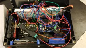
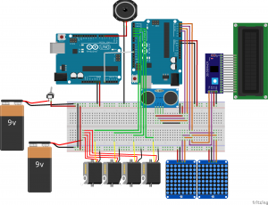
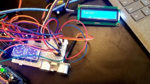
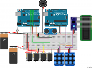
For my second milestone, I integrated the different components together. Specifically, I connected the Wave Shield, ultrasonic sensor, two servos to control the head, two servos to control the eyebrows, an LCD screen, and 2 LED matrices to act as the eyes. For the actual robot there will be many animations, but for right now the components are set up as follows: If the ultrasonic sensor determines there is something close to it, it triggers the animation in the Arduino. The speaker plays a sound (currently a “boing” sound), all four servos go from 180 to 90 to 0 degrees, the LCD screen shows the word “Danger!”, and the LED matrices show smiley faces. This serves as a proof-of-concept that the finished project will be able to fluently integrate all its inner components.
How it works
Four libraries are used to make this happen: WaveHC, ServoTimer2, Adafruit_LED_Backpack, and LiquidCrystal_I2C, the last two of which work on I2C ports. I2C stands for Inter Integrated Circuits, and is a communication protocol for connecting multiple devices together. The timer used by the WaveHC library conflict with the timers used for I2C devices, which, for now, cannot be avoided. To work around this, I got two Arduinos to work together. In their relationship, one device is considered the primary, which has complete control over all the logic and processing, while the other is a secondary, and controls only one component. In my case, the primary Arduino controls the sensor, servos, and overall logic. It sends control signals to the secondary Arduino, which can then control the LED matrices and LCD screen. First, the ultrasonic sensor sends out a pulse of sound waves and waits for them to bounce back. Depending on how long they take, the sensor can determine how far away the object they bounced off of is. If it is within a certain distance, currently around 7cm, then the animation starts. Since I am using the ServoTimer2 library instead of the standard Servo library, I cannot simply send the desired angle. Instead, I have to send a voltage fluctuation with a certain delay between each high and low, which determines the angle made by the servo. This is how the Servo library works as well, except here, I have to calculate the delay myself. This can be done using the equation (25/3 * <angle>) + 750. Meanwhile, the primary Arduino sends a signal to the A0 pin on the secondary Arduino, which tells it to start animating the LCD and LED matrices. Those are standard operations made simple by the library. The only problem with this is that both Arduinos need to be powered enough so they can control their components individually. For now, I power one with a battery pack and the other with my computer. Soon I will wire all the components to work solely off the battery pack (and remove their power requirements from the Arduino).
Code for the primary Arduino
	/*
		Specs on UNO
			Storage space: 33%
			dynamic memory: 75%

		pin wiring:
			A0 – > BUILTIN
			A1 – > Free
			A2 – > Ultrasonic trigger [TRIGGER]
			A3 – > Ultrasonic echo [ECHO]
			A4 – > I2C SDA – temporarily moved to secondary Arduino
			A5 – > I2C SCL – temporarily moved to secondary Arduino
			0 – > RX (Serial output)
			1 – > TX (Serial input – will be used for Bluetooth)
			2 – > Wave Shield
			3 – > Wave Shield
			4 – > Wave Shield
			5 – > Wave Shield
			6 – > Pivot servo [PIVOT]
			7 – > Lift servo [LEFI]
			8 – > Left eyebrow servo [LEFT_EYEBROW]
			9 – > Right eyebrow servo [RIGHT_EYEBROW]
			10 – > Wave Shield
			11 – > Wave Shield
			12 – > Wave Shield
			13 – > Wave Shield
	*/

	#include <WaveHC.h>
	#include <ServoTimer2.h>

	#define PIVOT 6
	#define LIFT 7
	#define BUILTIN A0
	#define TRIGGER A2
	#define ECHO A3
	#define LEFT_EYEBROW 8
	#define RIGHT_EYEBROW 9

	#define SENSOR_THRESHOLD 7

	// When using ServoTimer2, you need to send the width of the voltage pulse,
	// not an angle. These are used in getPulse(int) to calculate the width
	// based on the desired angle
	const float slope = (float)25/3;
	const float intercept = 750;

	// Using ServoTimer2 instead of Servo since
	// the Wave Shield uses the default timer
	ServoTimer2 pivot, lift, left_eyebrow, right_eyebrow;

	// Variables for reading the SD card
	FatReader root;     // keep a reference to the root directory
	FatVolume volume;  // Needed for reading the SD card
	SdReader sdCard;  // declare the SD card

	bool isApproaching() {
		/* This function returns whether the user is close to the sensor */

		// Flush the current
		digitalWrite(TRIGGER, LOW);
		delayMicroseconds(2);

		// Trigger a 10 micro-second sound wave
		digitalWrite(TRIGGER, HIGH);
		delayMicroseconds(10);
		digitalWrite(TRIGGER, LOW);

		// Read the incoming sound wave
		long distance = pulseIn(ECHO, HIGH) * 0.034 / 2;

		// Returns the distance (I'm relatively sure it's cm)
		return distance < SENSOR_THRESHOLD;
	}

	void play(String stringName, bool interrupt) {
		// Plays the name of this file
		// REMINDER: Wave File names need to be all-caps

		// Copy the filename to a char array
		int length = stringName.length() + 2;  // get the length of the filename
		char name[length];  // declare the array
		stringName.toCharArray(name, length);  // store the string in the array

		// Actually play the file
		WaveHC wave;  // store audio data
		FatReader file;  // declare the file
		Serial.print("Playing ");
		Serial.println(name);
		if (!file.open (root, name)) {  // store data in the file
			Serial.print(stringName);
			Serial.println (" does not exist");
			return;
		}

		if (!wave.create (file))  {  // Invalid .wav file
			Serial.println ("Not a valid wave file");
			return;
		}
		wave.play();  // actually play the .wav file
		if (interrupt) {  // need to stop all other code
			while (wave.isplaying) {  // print dots to the Serial monitor
				Serial.print(".");
				delay (100);
			}
		}
	}

	float getPulse (int angle) {
		// ServoTimers need a pulse width instead of an angle
		// formula here is: (25/3)(angle) + 750
		// constants are defined at the top of the file
		return (slope * angle) + intercept;
	}

	void setup() {
		Serial.begin (9600);
		pinMode (BUILTIN, OUTPUT);

		// Setup SD card
		Serial.println("Initializing SD card...");
		if (!sdCard.init()) Serial.println ("Card could not be read");
		sdCard.partialBlockRead(true);  // Cool little trick for faster reading
		// This just initializes file reading and writing
		if (!volume.init(sdCard)) Serial.println ("Volume could not be opened");
		if (!root.openRoot(volume)) Serial.println ("Root could not be opened");
		Serial.println ("Card initialized");

		// Setup servos
		pivot.attach (PIVOT);
		lift.attach (LIFT);
		left_eyebrow.attach (LEFT_EYEBROW);
		right_eyebrow.attach (RIGHT_EYEBROW);

		// Sensor setup
		pinMode (TRIGGER, OUTPUT);
		pinMode (ECHO, INPUT);
	}


	void loop(){
		if (isApproaching()) {
			Serial.println ("Sensor triggered");
			// Audio control

			play("TEMP.WAV", false);

			// Servo sweep
			digitalWrite(BUILTIN, HIGH);
			float pulse;
			// set servos to 0
			pulse = getPulse(0);
			pivot.write (pulse);
			lift.write (pulse);
			left_eyebrow.write (pulse);
			right_eyebrow.write (pulse);
			delay (1000);  // allow time from 180 to 0
			// set servos to 90
			pulse = getPulse(90);
			pivot.write (pulse);
			lift.write (pulse);
			left_eyebrow.write (pulse);
			right_eyebrow.write (pulse);
			delay (500);
			// Set servos to 180
			pulse = getPulse(180);
			pivot.write (pulse);
			lift.write (pulse);
			left_eyebrow.write (pulse);
			right_eyebrow.write (pulse);
			delay (500);
			digitalWrite(BUILTIN, LOW);
		}
	}
Code for the secondary Arduino
	/*
	Wiring diagram for the secondary Arduino (not with the Wave Shield):
	Arduino1 = Wave Shield (primary), Arduino2 = other one (secondary)
		primary GND to secondary GND
		primary Power (3.3 is fine) to secondary VIN
		primary A0 to secondary A0 (SIGNAL)
		I2C SCL to secondary A5
		I2C SDA to secondary A4

	Specs:
		Storage space: 24%
		Dynamic memory: 16%
*/

#include <Adafruit_LEDBackpack.h>
#include <LiquidCrystal_I2C.h>

#define SIGNAL A0
#define BUILTIN 13

// There is a nice website for editing LED matrix bitmaps
// My collection is stored at this permalink
// https://xantorohara.github.io/led-matrix-editor/#003c425a5a423c00|7e8181999981817e|003c420000000000|003c435a5c483000|003cc25a3a120c00|007e425a5a241800|1824429999819966
const uint8_t smile[8] = {
  B00111100,
  B01000010,
  B10100101,
  B10000001,
  B10100101,
  B10011001,
  B01000010,
  B00111100
};

Adafruit_8x8matrix matrix = Adafruit_8x8matrix();
LiquidCrystal_I2C lcd = LiquidCrystal_I2C(0x27, 16, 2);
// This is to keep track of when the signal comes and goes
bool processing = false;

bool gotSignal() {
	// Reads the SIGNAL pin
	int signal = digitalRead(SIGNAL);
	return signal == HIGH;
}

void drawBitmap(uint8_t bitmap[8]) {
	/* This function draws a bitmap onto the LED Matrix */

	// drapBitmap(int x, int y, int bitmap[8], int width, int height, bool status)
	matrix.drawBitmap (0, 0, bitmap, 8, 8, LED_ON);
	matrix.writeDisplay();  // needed to update matrix
}

void clearMatrix() {
	matrix.clear();
	matrix.writeDisplay();  // refresh matrix
}

void activate() {
	drawBitmap(smile);
	lcd.print ("Danger!");
	digitalWrite (BUILTIN, HIGH);
}

void clear() {
	// Resets the matrix, LCD, and BUILTIN
	clearMatrix();
	lcd.clear();
	digitalWrite(BUILTIN, LOW);
}


void setup() {
	// Basic setup
	matrix.begin(0x70);
	lcd.init();
	lcd.backlight();
	lcd.clear();
	pinMode (SIGNAL, INPUT);
	pinMode (BUILTIN, OUTPUT);
}

void loop() {
	/*
		Here, we want to be sure not to act unless the signal changes
		Control flow is basically a truth table:
			+-------+-------+
			|  Busy | Signal|
			+-------+-------+
			| True  | True  | ==> nothing
			+-------+-------+
			| True  | False | ==> clear devices
			+-------+-------+
			| False | True  | ==> Start devices
			+-------+-------+
			| False | False | ==> nothing
			+-------+-------+
	*/
	if (processing) {  // busy
		if (!gotSignal()) {  // shouldn't be busy anymore
			processing = false;
			clear();
		}
	} else if (gotSignal()) {  // not busy but should be
		processing = true;
		activate();
	}
	delay (100);  // IDK, just be a bit efficient
}

// some other matrix methods include:
// .clear()
// .writeDisplay()
// .drawBitmap(x, y, uint8_t bitmap, width, height, LED_ON)
// .drawPixel (x, y, LED_ON/LED_OFF)
// .drawLine (x1, y1, x2, y2, LED_ON)
// .drawRect (x1, y1, x2, y2, LED_ON)
// .fillRect (x1, y1, x2, y2, LED_ON)
// .drawCircle (x, y, radius, LED_ON)
// .setTextSize (1)
// .setTextWrap (bool)
// .setTextColor(LED_ON)
// .setCursor (x, y)
// .setRotation (1-4)
Reflections
While starting this milestone seemed simple enough, there were in fact several challenges that popped up. For one, the timer conflicts between the servos, LCD screen, LED matrices, and the Wave Shield forced me to dive deeper into how different libraries can impact each other. Eventually, I was forced to resort to using two different Arduinos, but in the future, I hope to dive deeper into the internal workings of the Arduino and manage to get everything working on one device. However, using two Arduinos has helped me manage each device’s responsibilities more efficiently. One important detail I learned here was that to have two or more devices communicate, they all have to share a common ground. I also had to deal with using three I2C devices with only 1 I2C-compatible port. Turns out, you can use multiple I2C devices on the same pins without any interference so long as they have distinct I2C addresses. Even though this milestone was a challenge to get working, doing so gave me the skills needed to face similar problems in the future and the rest of the project. Now that the internal components are all in working order, I can design and print the outside shell of the robot and finish the project.
First Milestone
My first milestone was to assemble the wave shield. Its job is to play audio (.wav) files off an SD card. It can play through a speaker or an audio jack if present. There is also a dial to control the volume.
How the Wave Shield works
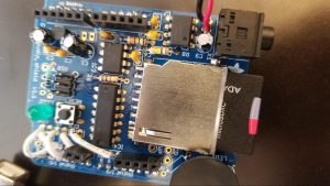
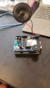
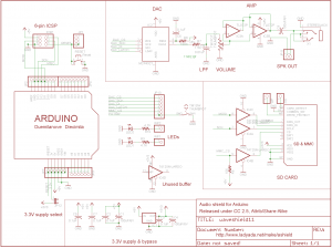
The wave shield connects to an arduino and replaces all of its pins. It has an SD card reader to read the audio files. There are three prominent chips on the shield, which you can see in Figure 1. The first one is a DAC, or Digital to Analog Converter, next to the long chip in Figure 1. It takes the digital signals from the SD card and converts it to analog for the speaker to play. The long one mentioned above is a buffer gate, which serves to amplify the signal coming from the shield, as well as to control the timing of all the different signals. The small chips on top of the SD card reader are operational amplifiers, which allows the components to only be powered by the power source instead of the arduino.
Scattered throughout the shield are (electrolytic) capacitors (the black cylinders and orange bits in Figure 1), a transistor (sandwiched between the two electrolytic capacitors), and resistors (like between the DAC and buffer gate) to regulate the current in the circuit. There is a dual-channel potentiometer in the bottom-right corner (more visible in Figure 2) to control the volume. When the potentiometer is turned, it blocks power from going to the speaker/headphone jack, which in turn lowers the volume. Finally, to integrate the shield with the Arduino, I had to solder male headers on the bottom of the shield (to connect to the Arduino’s female headers), and then add female headers to the top to expose connections for other components. Unfortunately, I was not able to use all the pins, as pins 2, 3, 4, 5 and 10 are used by the shield for SD card operations. In order to get visible indication of the Arduino’s status, I soldered an LED and resistor to the shield and connected it to pin 13, to mimic the built-in LED. I will also do this for the 5V pin, to turn it into a power indicator.
Code
	/*
		REMINDER: File names need to be all-caps

		Specs on UNO
			Storage space: 27%
			Dynamic memory: 71%

		pins that still work with audio:
			A0,
			A1,
			A2,
			A3,
			A4,
			A5,
			6, (BUILTIN,
			7,
			8,
			9,
	*/

	#include

	WaveHC wave;  // store audio data
	FatReader root, file;  // Needed for reading the SD card
	FatVolume volume = FatVolume();  // Needed for reading the SD card
	SdReader sdCard = SdReader();  // declare the SD card

	void play(String stringName, bool interrupt) {
		// Copy the filename to a char array
		int length = stringName.length() + 2;  // get the length of the filename
		char name[length];  // declare the array
		stringName.toCharArray(name, length);  // store the string in the array

		// Actually play the file
		Serial.print("Playing ");
		Serial.println(name);
		file.open (root, name);  // store data in the file
		if (!wave.create (file))  // Invalid .wav file
			Serial.println ("Not a valid wave file");
		wave.play();  // actually play the .wav file
		if (interrupt) {  // need to stop all other code
			while (wave.isplaying) {  // print dots to the Serial monitor
				Serial.print(".");
				delay (100);
			}
		}
	}

	void setup() {
		Serial.begin (9600);
		Serial.println("Initializing SD card...");

		delay (1000);
		if (!sdCard.init()) Serial.println ("Card could not be read");
		sdCard.partialBlockRead(true);  // Cool little trick for faster reading
		// This just initializes file reading and writing
		if (!volume.init(sdCard)) Serial.println ("Volume could not be opened");
		if (!root.openRoot(volume)) Serial.println ("Root could not be opened");

		Serial.println ("Card initialized");
	}

	void loop(){
		play("TEMP.WAV", true);  // true means to wait for file to be over
	}
Reflections
Making the wave shield proved to be a challenge. For starters, I never soldered this much — or with components so delicate, such as chips and the SD card reader. I also barely work with shields, so having to provide a stable interface to the Arduino was nerve-racking. I also learned the importance of power regulation. The majority of the components on the shield are simply to protect the other components from damage. I also learned how speakers work (and that they do not need to be polarized) as well as how to read data from an SD card using the SD library. Another cool part of this milestone was personalizing it. By soldering on two LEDs and wiring them to my liking, I was able to get useful functionality without resorting to a tutorial.
One big problem with the wave shield is that it is configured to use a library where the author took liberties. Instead of using the standard SD library, he rewrote parts of it to be incompatible, thus forcing me to convert all my code to use his library. The library itself takes >70% of the Arduino’s memory, and since the shield is for the UNO, I cannot simply switch to a MEGA, or other device. This may lead to problems down the line, but I am sure I can fix it later.
Starter Project
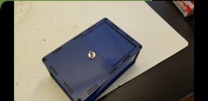
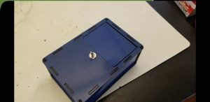
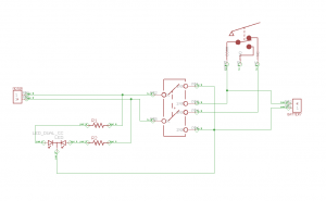
For my starter project, I made the Useless Machine, which is basically a simple box with a switch. The switch starts off leaning forward, as in Figure 1. When the switch is flipped, an arm comes out of the box and flips the switch back. The circuit is in such a way that when the switch is pointing back, the signal sent to the arm’s motor tells it to go forward. The arm is aligned so that it will hit the switch back to its original position, as shown in Figure 2. When this happens, a signal is sent to turn the motor in reverse until the arm hits a kill switch, ending the process. Figure 3 shows a circuit diagram for this project.
From doing this project, I realized how much hardware can achieve without software. Instead of using the switches as input and programmatically controlling the motor, the current naturally flows to do the same job. During construction of the outer box, I accidentally screwed the acrylics on upside-down, which was frustrating later on, but then was able to simply reverse it and everything worked again. Also, the screws holding the whole box together did not go in right, and it was hard to get it to stay together. But overall it was a very simple process. Now that I have finished my starter project, I am ready to move on to my more complicated main project.


