Solar Power MP3 Player
There are 4 components to the Solar Power MP3 Player: The solar charger, the audio, the code for the button and LCD screen, and the physical enclosure of the structure. The buttons and LCD screen run on Arduino and the speaker and charger use lithium batteries. The final result will be a box with a solar panel on top, buttons and a screen on the side , and all the electronics inside.
Engineer
Leah S
Area of interest
Medicine
School
SAR High School
Grade
Rising Junior
Final Milestone
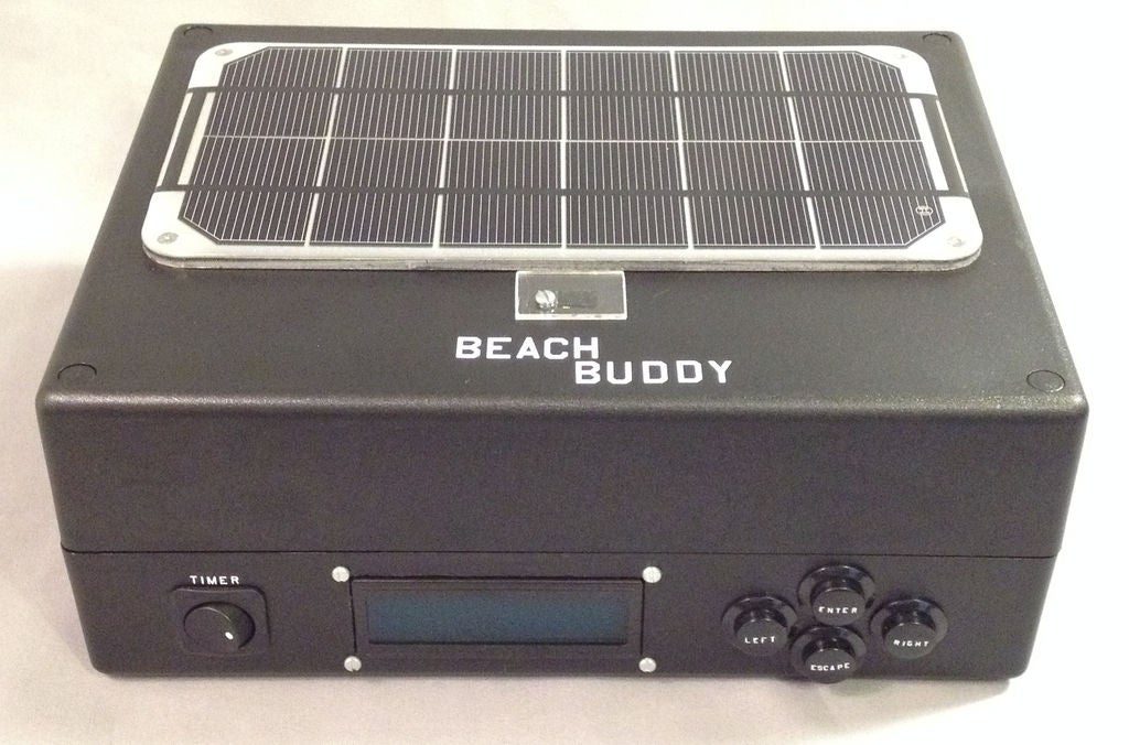
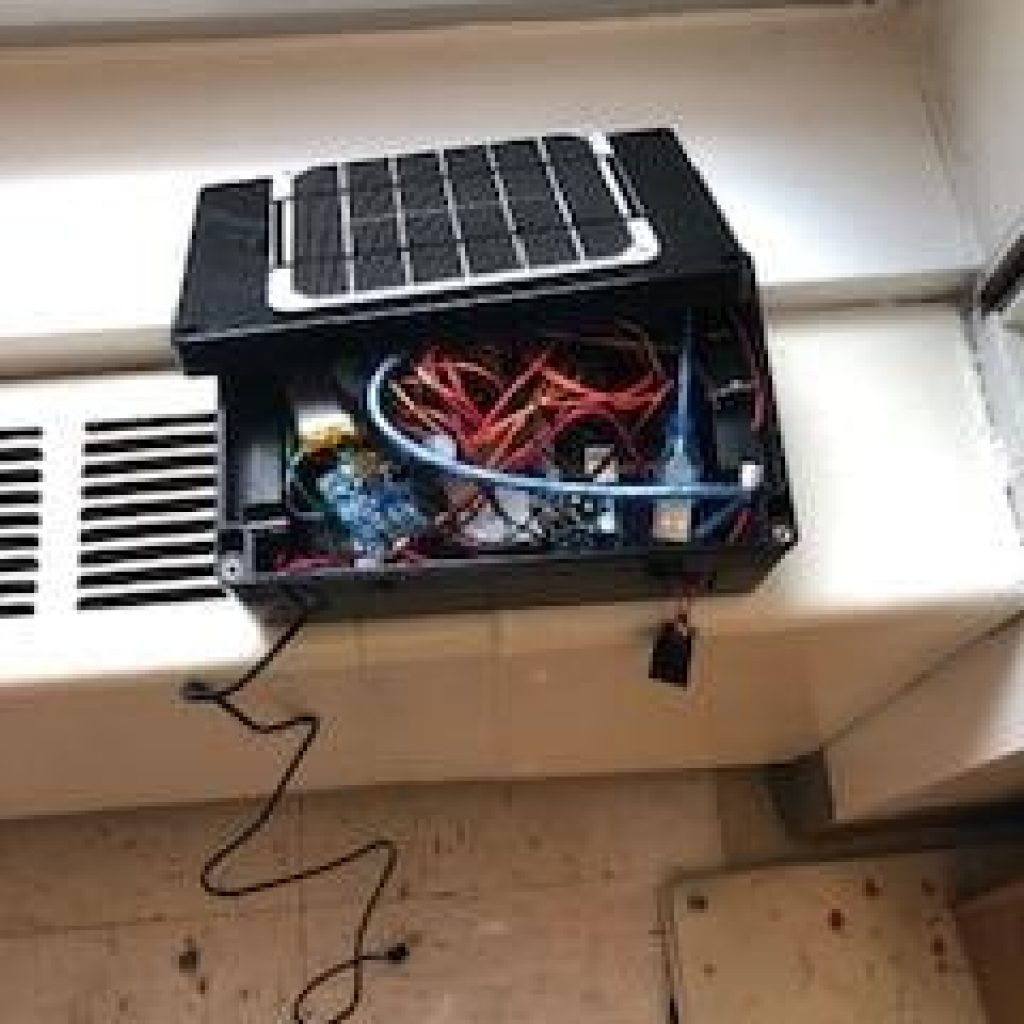
My final milestone is completing my solar powered MP3 player. I connected the Arduino to the minty boost to give it power. this allows the LCD screen and buttons to work. I then connected the speaker button to power and ground on the Arduino so it could also be powered by the solar charger. The whole project is powered by the solar panel which pushes energy into the power capacitor into the minty boost which outputs usable energy and powers my project. In conclusion I have a fully functioning solar power MP3 player.
The solar panel MP3 player with all the wires connected allowing power to be distributed
Third Milestone
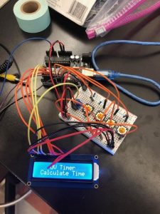
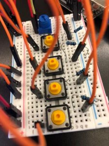
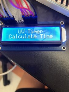
My third milestone was to connect the LCD screen and control what it is displaying using four buttons. You can see the LCD circuit on the left, I had to make sure that the power was connected to 5V instead of 3.3V. The buttons function as four different inputs, controlling different functions in the mp3 player menu. The buttons control left, right, enter, and escape.
Below is a segment of my code that reads the buttons’ inputs to control the menu. The menu has options that you select using the buttons. This code allows the input to be used and select a certain option in the menu.
void  readButtons(){  //read buttons status
  int reading;
  int buttonEnterState=LOW;             // the current reading from the Enter input pin
  int buttonEscState=LOW;             // the current reading from the input pin
  int buttonLeftState=LOW;             // the current reading from the input pin
  int buttonRightState=LOW;             // the current reading from the input pin

/*-----------------------------------------*/
//ENTER button:
  reading = digitalRead(buttonPinEnter);
  //Serial.println(reading);
  //delay(500);
  if (reading != lastButtonEnterState) {
    lastEnterDebounceTime = millis();
  }
  if ((millis() - lastEnterDebounceTime) > debounceDelay) {
    buttonEnterState=reading;
    lastEnterDebounceTime=millis();
    //Serial.println(reading);
  }
  lastButtonEnterState = reading;
A fully functioning LCD screen controlled by buttons
Four buttons that control the LCD screen
The LCD screen that displays all the options
Second Milestone
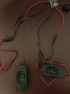
The speakers connected to thew MAX98306 using female ad male wires
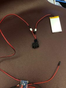
The switch connected to the MAX98306 and battery
The fully functioning boombox
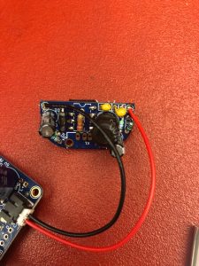
The PigTail wire that allows for the boombox to be plugged in
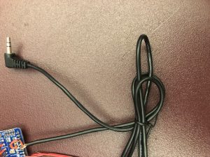
My second milestone is assembling and testing the boom box: the audio portion of the project. I started by soldering wires to the MAX98306 a stereo amplifier which enlarges the sound inputs it receives. I then soldered a PigTail (aux cable) into the board to allow for the usage of the boombox later. Following that I attached the speakers to the circuit by attaching four male wires to left and right output and four female wires to the ends of the speakers. Now I was able to connect the speakers to the MAX98306 which allows you to play the amplified sound. I connected the switch to the lithium polymer battery and JTS extension so I can control when the amplifier is on. This allows the amplifier to be turned off with a switch of a button because one side is connected to the power and one side to ground. Finally to test this out I plugged it into my computer and played music. It properly played music through the speakers because the circuit was complete and had a power source.
First Milestone
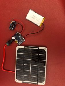
The fully functioning solar powered battery
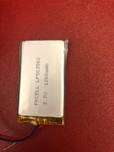
The battery that stores the power
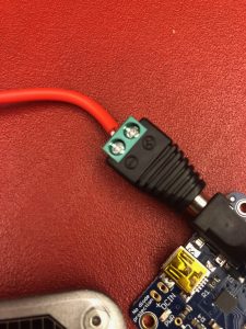
The DC power plug that is the connector for supplying direct current power
The minty boost that filters and stores the electric energy
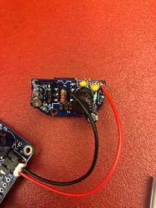
My first milestone is assembling and testing the solar charger. I began by soldering in an electrolytic capacitor into the TPA2016 to store the energy in the charger. I then took the solar panel and striped the wire attached to it to make it compatible with the DC (direct current) barrel plug so it could be plugged into the board. You need the DC barrel plug to connect the DC electricity and supply the direct current power which allows for the usage of the power. After I connected the solar panel to the TPA2016 I connected a minty boost and a 1200mAh lithium polymer battery to the TPA2016. This provides storage and filtration for the energy. For the minty boost I soldered in two Power supply capacitor and two Bypass capacitor (0.1uF). I also soldered in three different kinds of resistors. Finally to test this I used a multi meter to ensure the battery is working and my solar powered battery contained .5 volts in indoor conditions. Although this is low taking into account the lack of sunlight it is actually pretty high. In conclusion I made a fully functioning solar powered charger.
Simon Says
Figure 1: Full picture of Simon Says project.
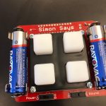
Figure 3: The on and off switches that allow the game to begin or end
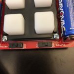
Figure 5: the AA batteries that power the game
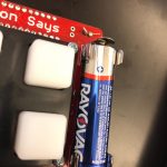
Figure 7: the speaker that emits sound when buttons are played or pressed.
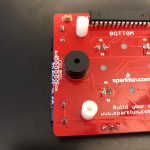
Figure 2: A light being turned on by program that user is supposed to mimic .
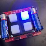
Figure 4: the micro controller which controls the game is at the top.
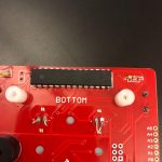
Figure 6: the soldered ends of all the wires that allow the game to work

My starter project is Simon says which is a game of mirroring. The player must copy the program by clicking the buttons in the same order that they light up. It gets quite challenging as you get to later rounds because it presses your memory. How it works is once both the power and sound switches are turned on, a random sequence is generated and used to light up a light emitting diode (LED), which is an electrical component that lights up when power runs through it. It starts with just one LED then increases the sequence by one each round. After the sequence is played, the system waits until the player taps the buttons. If they tap correctly they move to the next round. If they tap incorrectly all the buttons light up displaying the game is over. This is all coded within the micro controller which is the brain of the game. It contains all the rules and steps that the game is going to go through. It is soldered on the ends to ensure that it’s connected to the circuit. The game has 4 LEDS covered by 4 buttons. These buttons are what the system reads and informs it how to move forward. The whole game is powered by 2 AA batteries. Then the charge is carried throughout by soldering the ends of the wires. This works because the solder is a good conductor of electricity. Finally a speaker is wired into the game to add sound effects and improve the game. It makes sounds when the computer plays the initial sequence and makes the same sound when you create the sequence.
If you fail to copy the sequence it makes a different sound indicating you lost. This game is an amazing starter project and I am so happy I had the opportunity to make it. I am so excited to expand my skills and start my main project.


