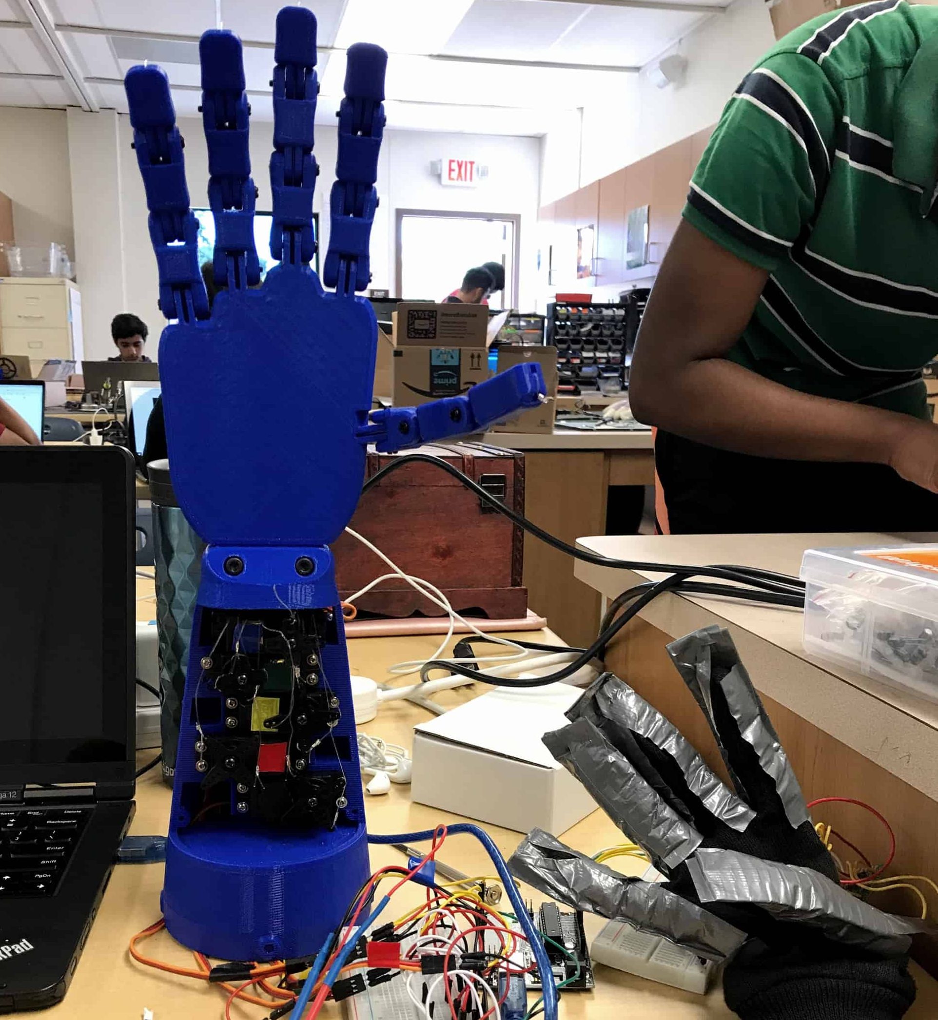
3D Printed Robotic Hand
This robotic hand can be controlled using a glove. For example, when the user points their index finger, the robot will do the same. Sensors in the glove communicate with servos in the robot using an Arduino Uno and code.
Engineer
Kriselle T.
Area of Interest
Electrical Engineering & Computer Science
School
Summit Public Schools: Rainier
Grade
Rising Senior
Reflection
My code, bill of materials, build plan, and schematics can be found on my GitHub.
The STL files used for this project, created by Unlimited Tomorrow, can be found here.
Final Milestone

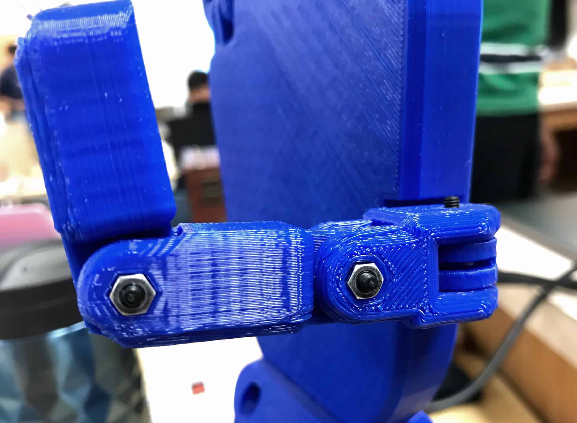
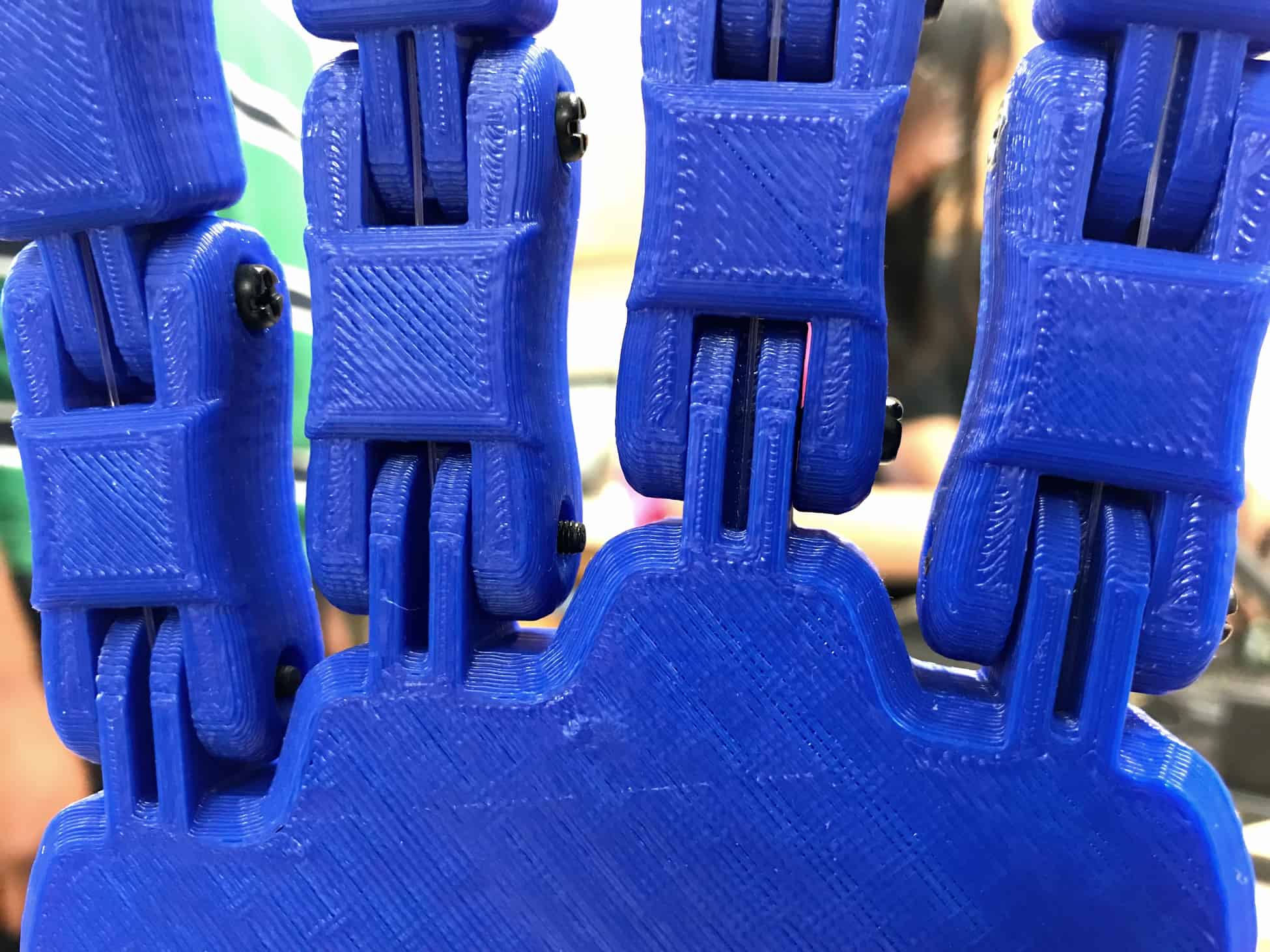
Assembling The Hand
To finish my base project, I had to assemble the parts for the 3D-printed hand. I separated the parts from their printed structures and used a file and sandpaper to clean the holes and surfaces of the hand. I ran fishing line through holes in the fingers and palm, then connected each joint using bolts and nuts.
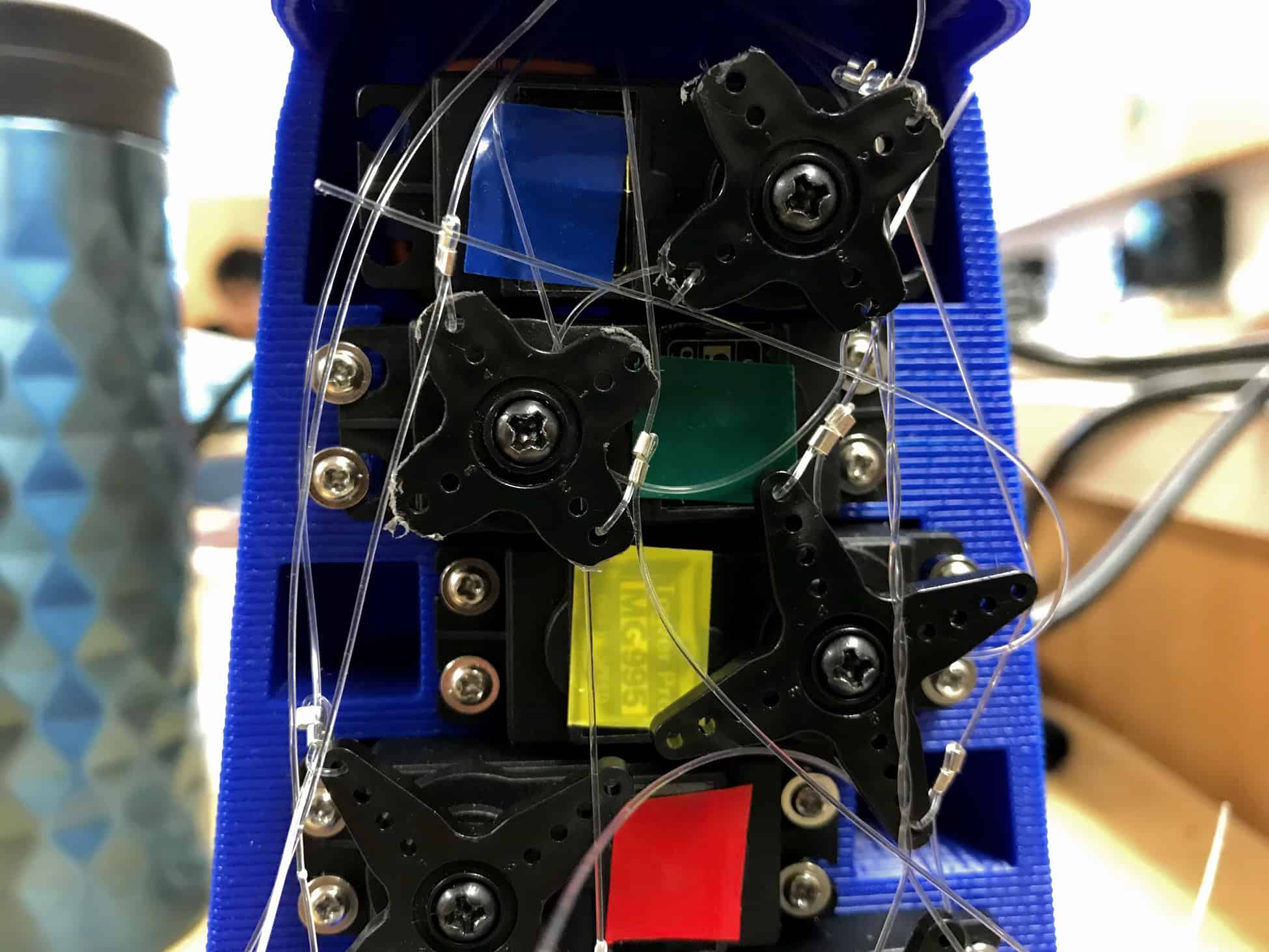
Installing Servos
Then, I had to connect the ends of the fishing line to the servos. I first had to permanently attach the servos to the hand in order to make sure that they didn’t move when powered. Because I wanted to use one more servo than the arm can hold, I had to superglue the extra servo into an empty slot. Because this space wasn’t meant to hold a servo, I had to drill a hole in the side of the hand to make space for the wires in the servo. For the other four servos, I used a dremel to create holes that I could use to screw the servos into.
Threading Fishing Line
Finally, I connected the fishing line to the horns of each servo. This was the most difficult part of the project. If one fishing line is too loose or too tight, the fingers won’t bend or straighten all the way, and the fishing line has to be uncrimped, adjusted, and crimped again. At one point, I resorted to cutting the fishing line and restarting everything.
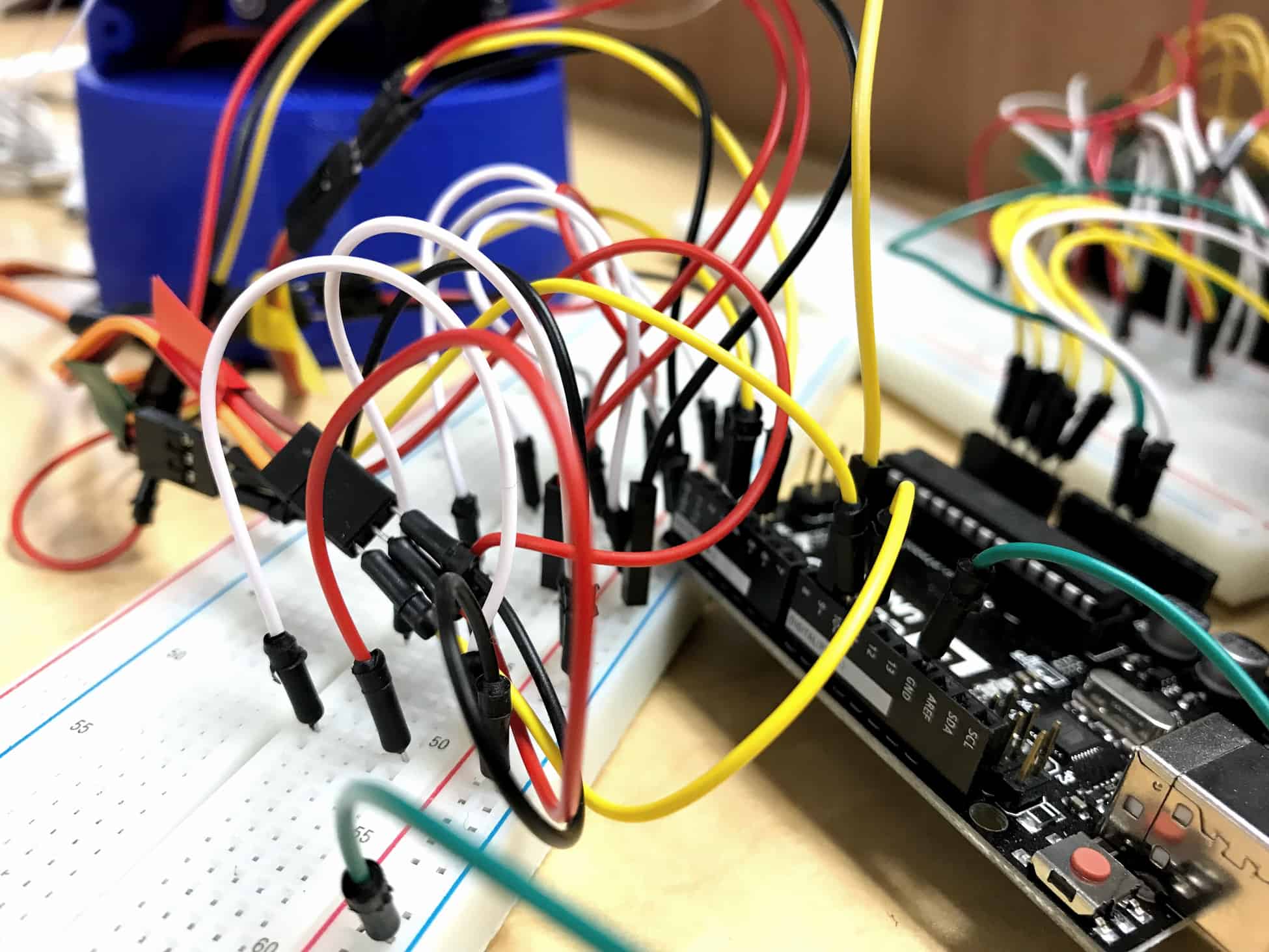
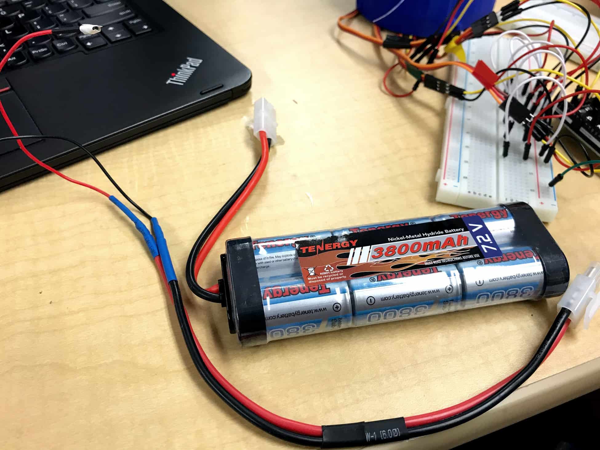
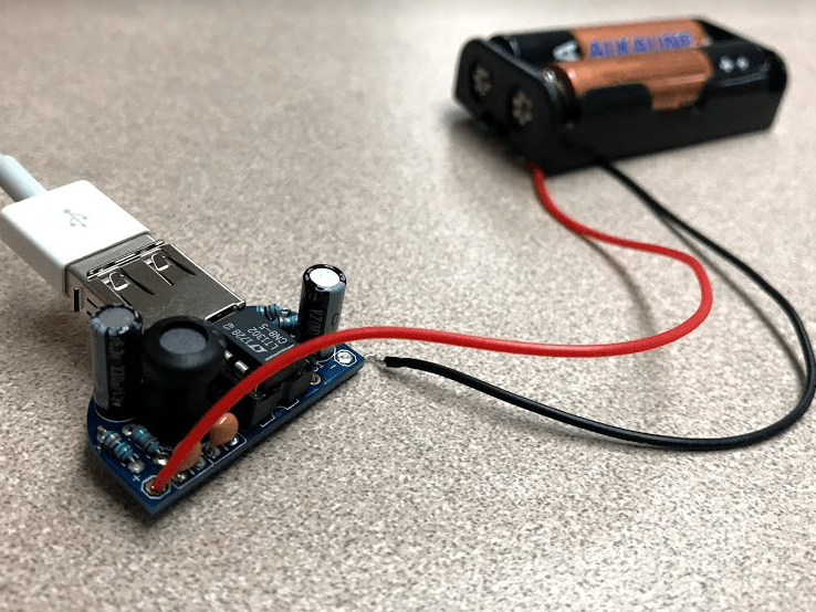
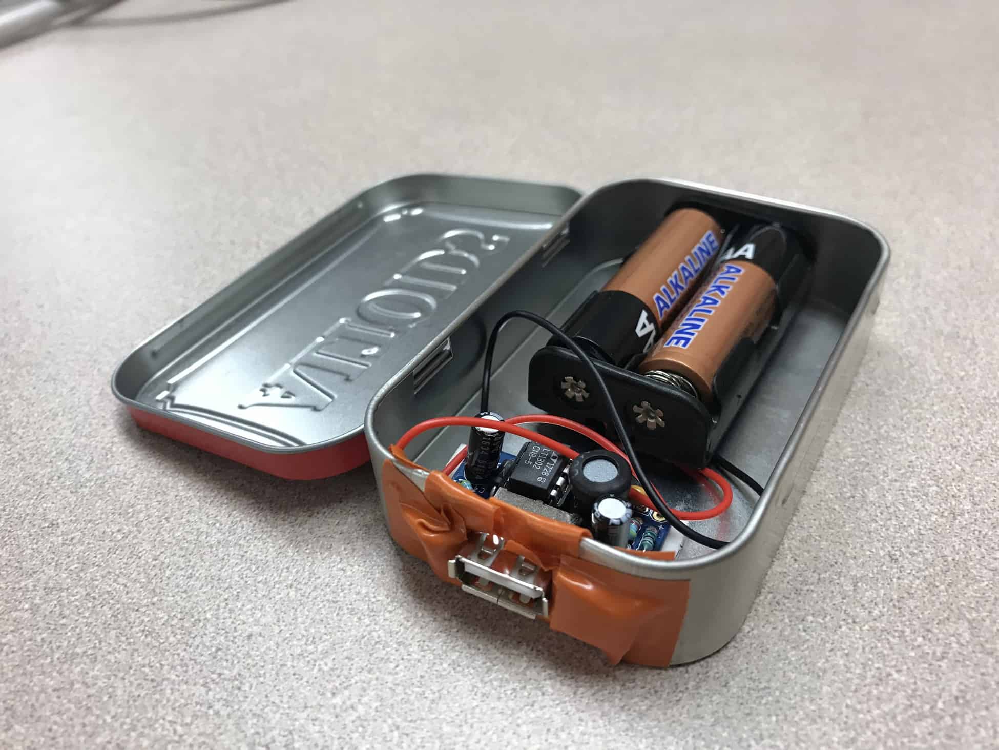
Powering The Servos
Before implementing it into my circuit, I used a multimeter to test the voltage of my battery. It was giving 8.5 to 9 volts instead of the 7.2 that I expected, so I added a voltage regulator to drop the voltage down. When my servos were connected to the battery, they spun for a few seconds before stopping. Each time I connected them to power, they spun for longer and longer periods of time until I couldn’t control them anymore. I wanted to find a way to stop this, since it would cause the fishing line to snap if it continued. I tried adding different potentiometers, resistors, and diodes until I realized that the circuit didn’t have too much current, it had too little. After I removed the regulator, the servos stopped spinning.
Future Plans
The orientation of the thumb’s base joint causes the finger to occasionally rotate instead of bend. If it’s possible, I want to replace this joint with one that does not rotate. The thumb also does not bend to it’s fullest ability because of the servo that it is attached to. If possible, I want to find a way to turn more efficiently. In addition, I plan on using XBee to make the connection between the glove and the hand work wirelessly.
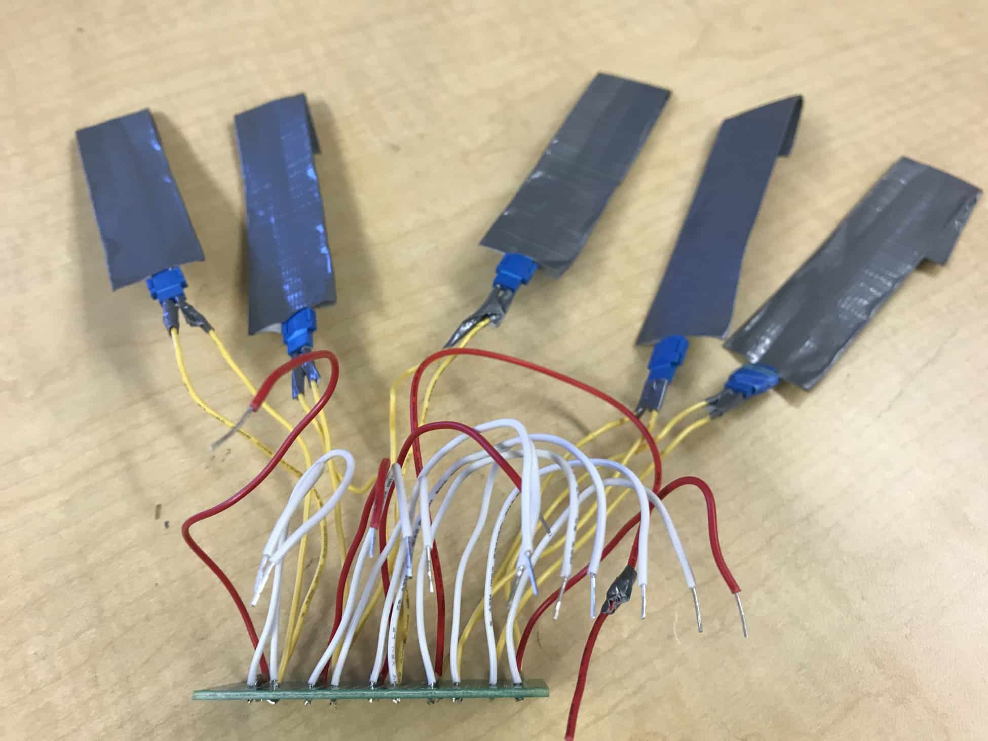
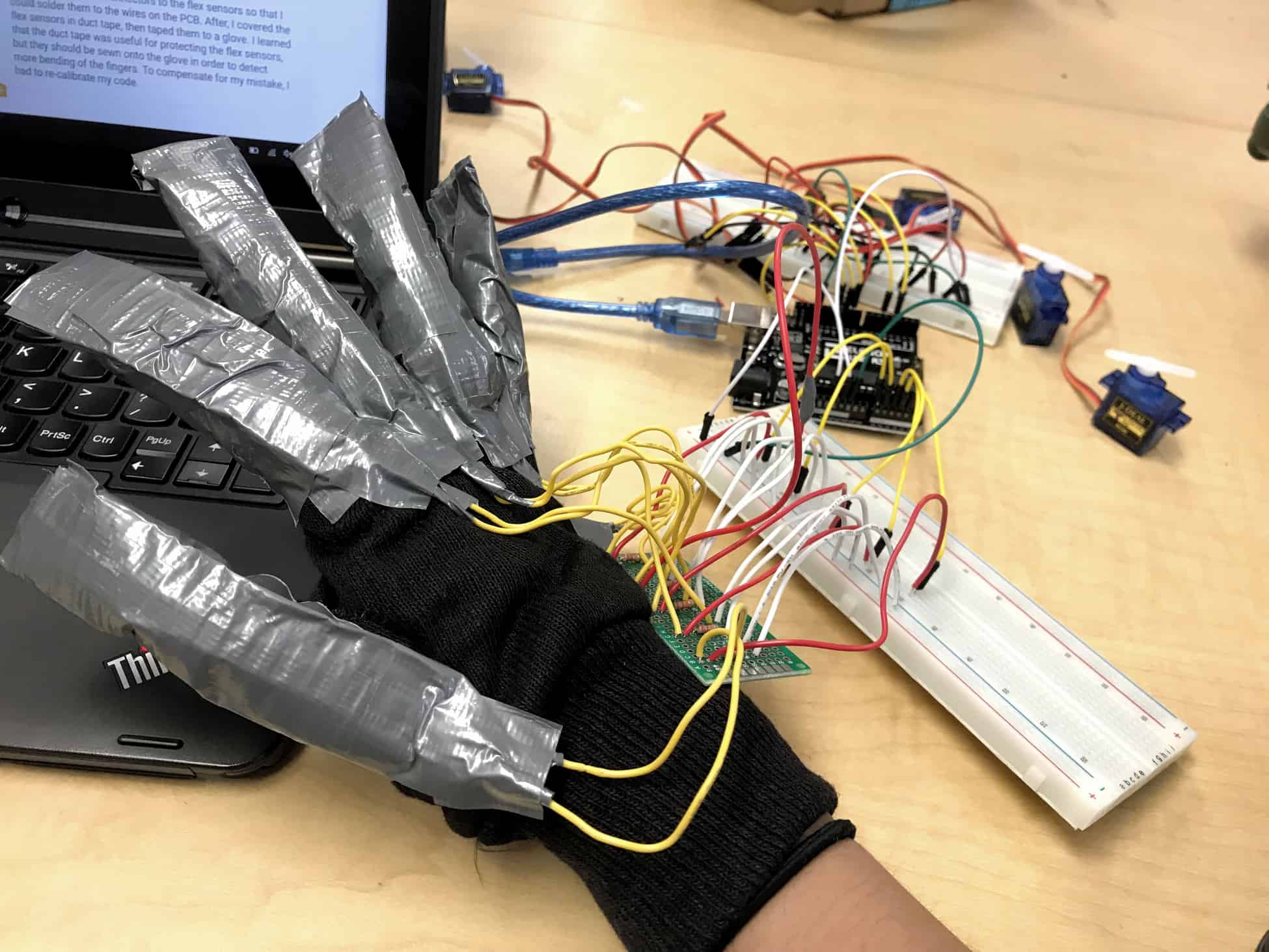
Second Milestone

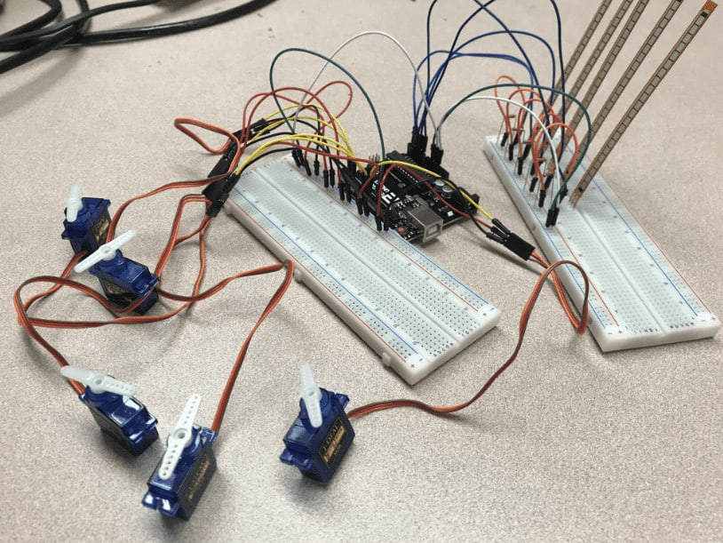
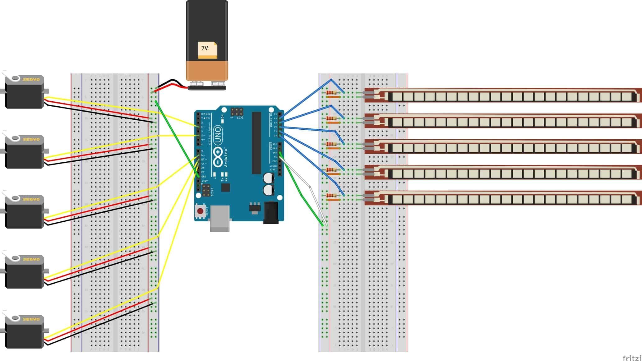
First Milestone
My code and schematic were based off of the projects of two previous BlueStamp students: Annabel Y. and Sanjana K. My code and schematic can be found here.
