
PCB Etcher
The PCB etcher is a specialized CNC that mills custom PCBs based on input g-code. The 3 main parts to the etcher are the frame, the motors, and the firmware. As such, I split my project into 3 milestones, each representing a stage of the project.
Engineer
Kosta D
Area of Interest
Finance/ Environmental Engineering
School
Stuyvesant High School
Grade
Rising Freshman
Reflection
Coming into Bluestamp I expected a super hardcore, all day engineering and work schedule with no socialization. My brother had come to Bluestamp in one of the prior years and built his own project, and from what I heard about Bluestamp from him it was a ton of work but you got to build what you wanted to. So, understandably I was very surprised on my first day when everyone was very social and friendly and when music was playing all day. I am extremely glad that Bluestamp has cultivated such a friendly and social community of young engineers, and I am also glad that I was able to be a part of that community, and that I was able to construct a project from my dreams. Being at Bluestamp has been an invaluable experience that has taught me plenty about documentation and engineering, as well as countless new interesting things from the daily guest speakers. Most of all, I am thankful for all the new connections and friendships I made at Bluestamp. In the future, I will continue learning about all the different branches of engineering, physics, math, and science. I am continually fascinated and surprised by new and interesting topics and concepts in the engineering world.
Final Milestone
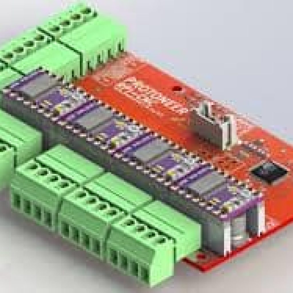
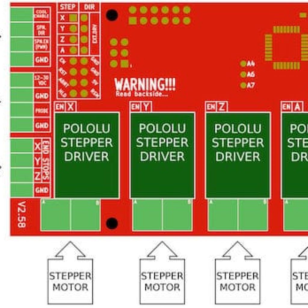
Milestone three is the final milestone, milestone 3 is to put the entire PMC together and run all of the motors from the preloaded bCNC software on the Rasberry Pi. To do this, I had to etch the 8GB Micro SD Card with Rasberry Pi CNC User Interface SD Card Image V4.10, the operating system for the Rasberry Pi 3, which also comes preloaded with all the software necessary for the CNC. The bCNC software is crucial to interfacing with the CNC because it utilizes the Serial port of the Rasberry Pi to send out GRBL signals. GRBL is open-source software that converts special commands in a text file to physical movements for the CNC. There is an entire wiki on the topic that covers all aspects of GRBL, including the various specialized commands. GRBL is popularly used in CNCs all over the world and is very useful in interfacing with them. Once I figured out how to set up the Rasberry Pi, I just had to set up the Protoneer CNC Hat/Shield for the Rasberry Pi. The Shield plugs directly into the pins on the Rasberry Pi and it requires plug-in drivers for the stepper motors, the Shield also has an Arduino Nano chip that arrives preprogrammed with GRBL so that it can interpret GRBL commands from bCNC. Other than plugging in the short jumpers under the drivers to verify the step size and actually plugging in the drivers, there isn’t much to set up. The only thing left to do is set up the wiring for the Shield, which uses screw terminals to securely fasten the wires to the board, the main wiring consists of plugging in the stepper motor wires, the limit switch wires, and the wires from the 12V-36V power supply. Once that is complete, I was able to control the motors with the bCNC software. However, I ran into some issues, for one, the drivers, even for the working motors, were overheating. But, there were motors that simply did not work, either from fried motor drivers or simply messed up ones. During the completion of this milestone I ran into some issues, first off, I had never used a Rasberry Pi before, so with the help of a fellow Bluestamp student and the trusty internet, I found multiple different tutorials on how to first etch the Micro Sd card, then replace the missing config, and finally on how to set up bCNC and open the serial port connection. I also learned various different g-code commands in the process of getting the PMC to work, the different flavors of g-code, and different settings/resolutions of steps. In the duration of this project, I learned how to document my work efficiently, clearly, neatly, and professionally. My experience at Bluestamp has been invaluable!
Second Milestone
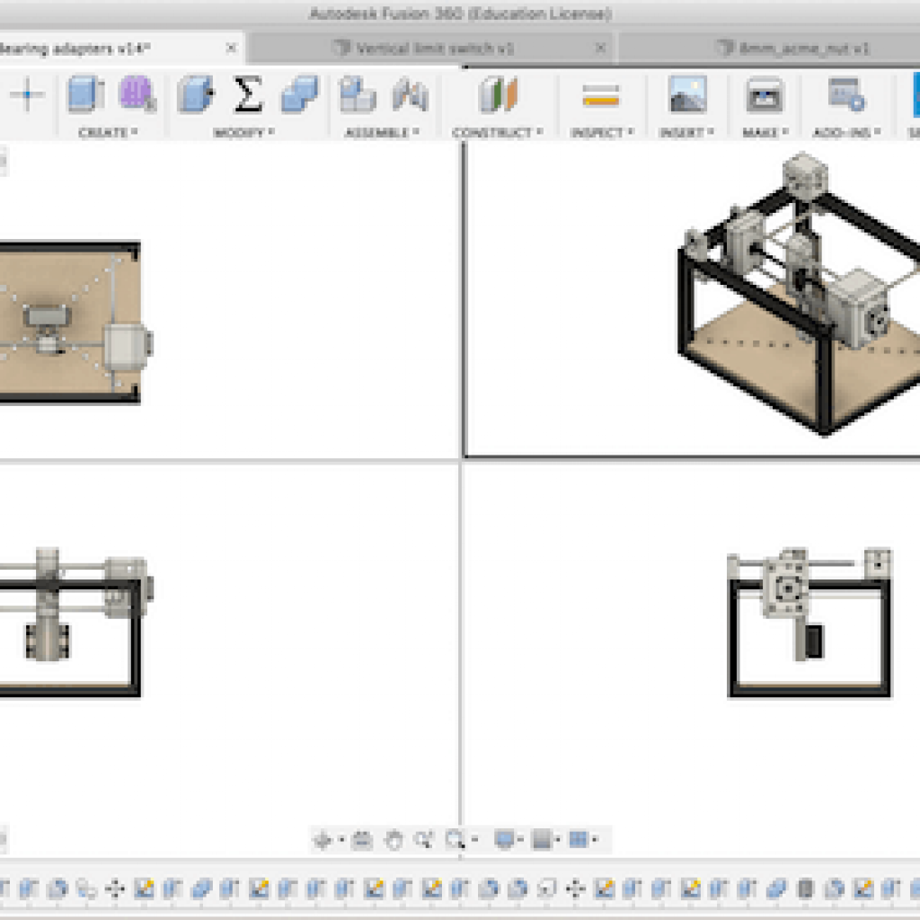
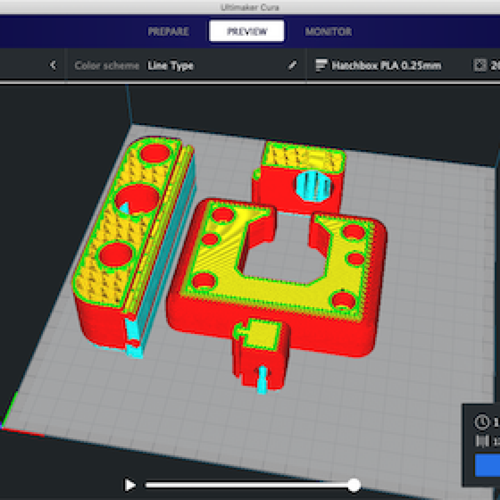
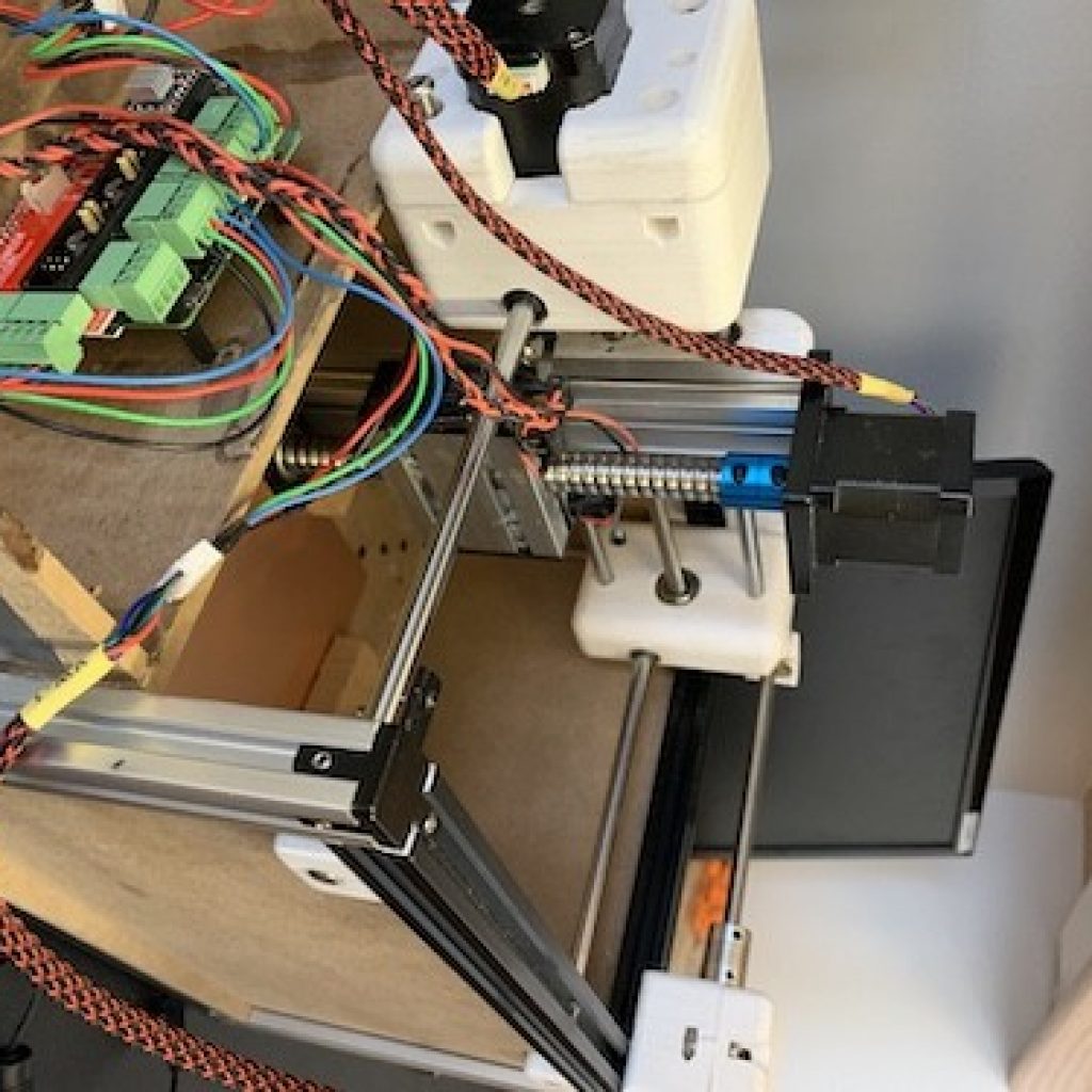
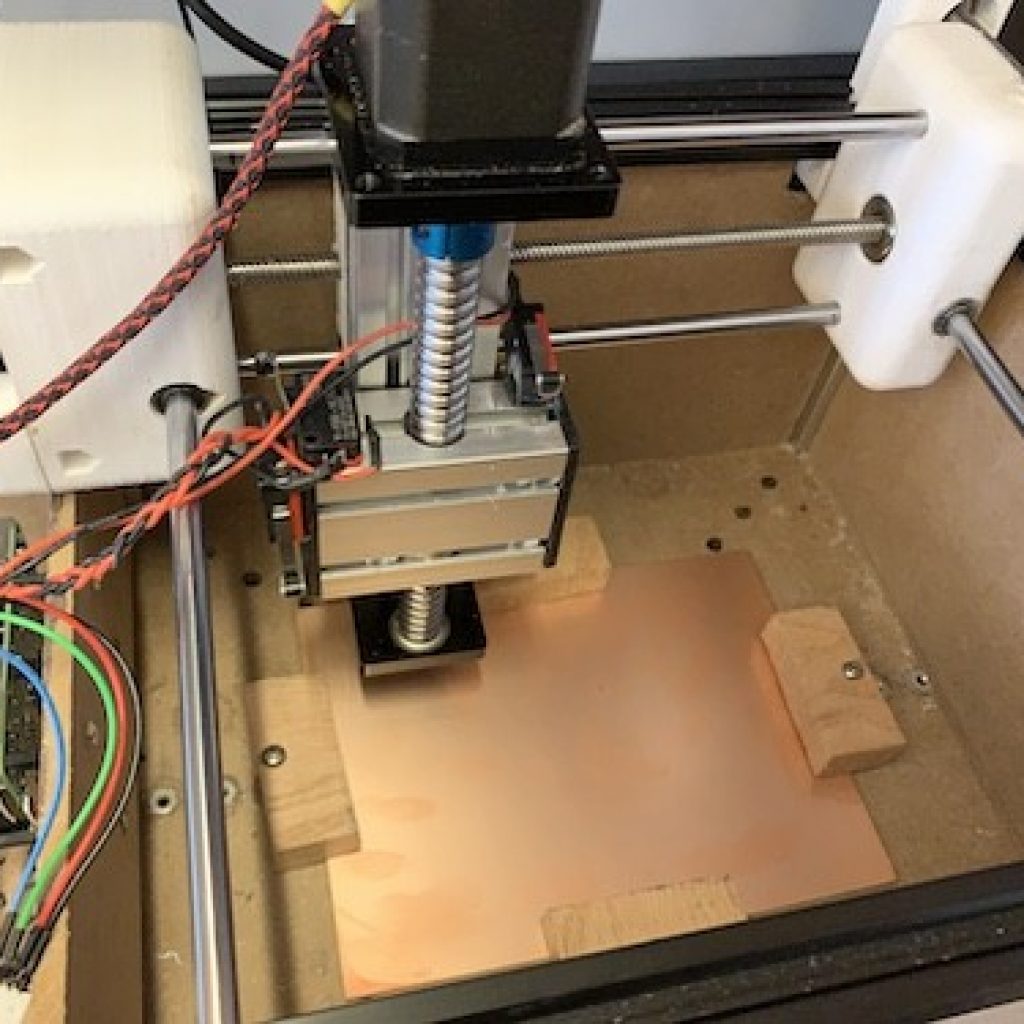
Milestone two is to machine all of the components and then assemble the frame of the PMC (PCB-milling-CNC). The frame holds all of the motors together and holds the axis in place. The frame is also a passive vibration dampener which absorbs shudders or resonance from the motors. The process of machining was far from perfect; in fact, it was a long frustrating process involving numerous incorrect measurements, skewed holes, missized cuts, and many, many, swings of a hammer to right things. However, the end product was a functioning XYZ linear axis motion control system. The assembled frame involved the aluminum extrusion skeleton, the MDF boards that make up the sides of the PMC, the MDF boards that make up the part holders and the dust collection, and the 3D printed parts that put the linear rails together. I learned how to use an exacto knife and various power tools to create the MDF frame. I also learned the importance of precise measurements and markings. Countless mismeasurements and skewed holes/cuts drove me crazy, and it took at least a dozen hours to construct the frame and even more to the CAD. The result is a sleek, professional looking, and sturdy system.
First Milestone
Completing Milestone 1
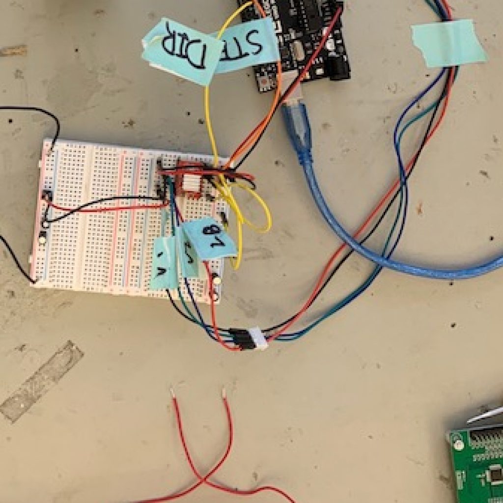
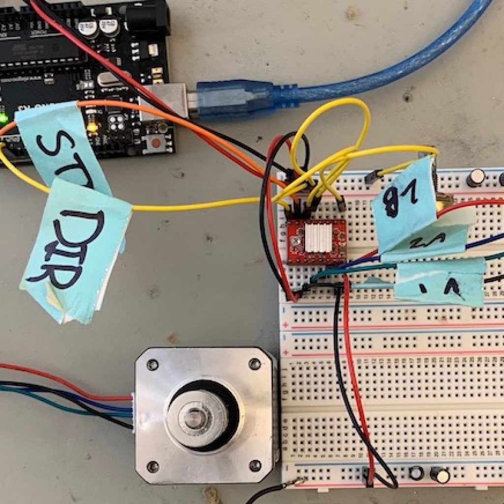
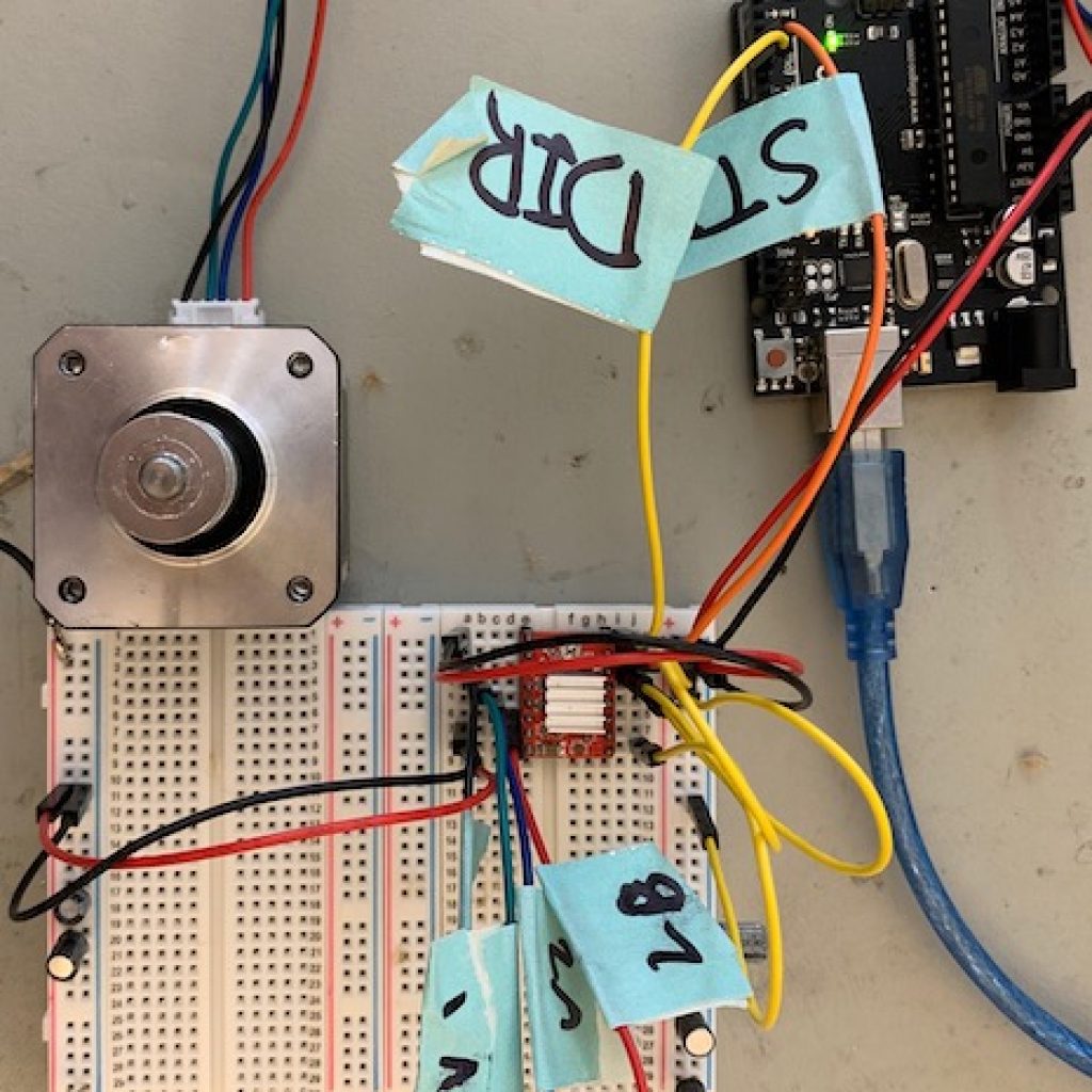
My project is a CNC that is specialized to etch PCBs, to accomplish this goal, I first had to accomplish milestone 1. Milestone 1 is to control one stepper motor at a time with the motor driver. Instead of using a driver board, we just plugged the motor driver into a breadboard and did all the connections manually. Basically, the driver takes in two inputs, 5V and 12V power. The 12V is used to power the motors and the 5V is used to power the 5V pin on the driver. Other than the power and power distribution on the breadboard the driver also takes in two inputs from the Arduino, DIR and STEPS, DIR stands for direction, the direction in which the stepper motor turns and STEPS is the number of steps that the motor will turn in the given direction. While striving to complete milestone 1 I ran into many different issues and errors. I had countless miswirings and as a result I blew up 4 capacitors. By the time I finally got the end result working I had also gone through countless iterations of code and 3 motor drivers. However, I learned the pinout of the driver and I learned how to control the driver without a shield or a board. Also, I finally got proof that the motors worked and that I could accurately control them.
Starter Project
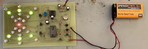
The Exploding Star Color Organ Kit is a circuit that spontaneously lights up LEDs in reaction to external sound that the microphone senses. There are 3 varieties of LEDs, red, yellow, and green, 12 red, 7 yellow, 6 green, all of which are arranged in a star shape on the PCB.
By completing the starter project I learned how to interpret and understand resistor coloring keys. Using the Resistor Color Code I was able to put the correct resistors into their appropriate positions on the PCB.
Despite the end result working, I encountered many challenges along the way, countless times I had to resolder and reposition components on the PCB. More than once I would burn through the copper trace and have to improvise and connection. The end result is a combination of trial and error, and tedious soldering.
This is a visual demonstration of the working final product.
How it works
This works by utilizing two different Integrated Circuits, better known as IC’s. The IC’s are visible on the PCB, they are the black rectangular components with text on top. The power from the battery is controlled by the various resistors, capacitors, and transistors to light up the LEDs in an outgoing ring pattern.
Mini POV Schematic
