
Hi! My name is Kiran C and I am a junior at Edmond North High School. My starter project is the mini piano, and my main project is a hydroponic farm system. It will be able to measure pH values and contain a watering system. My main interest in the hydroponic system was the fact that I could create something environmentally friendly and grow my own food. I am interested in environmental and biomedical engineering, and this project could help me get hands on experience and new opportunities to explore science and math related fields.
REFLECTIONS
After completing the BlueStamp program, I have definitely learned a lot about myself and where I see myself in the future. I came to BlueStamp to learn about engineering and what engineers really do. I wanted hands on experience in this field of science and a fun and interesting summer. I picked my project to be a hydroponic farming system because I like biology and to be outside most of my time. I was looking for a way to tie those things together with a learning experience. I hope to do science projects with my farm involving pH and acidity in the near future. Going in I thought my project would be very hard to complete, but it wasn’t as daunting as I expected it to be. My main worry about the project was the electrical components, but after learning about the simple parts of circuits it was easy to research and get a better understanding of how my project worked. The mechanical aspect of my project was easy to follow. A hard and tedious part was cutting some of the materials. One difficulty I encountered was leaks occurring in the return gutters. Originally I duct taped the gutters to the end caps. I then used hot glue and grout, but what really worked was using liquid nails, or PL. I learned a lot about electrical, mechanical, and software engineering by myself (through research) and with help from the instructors. The Arduino is the main part of my project, and I learned that I can build and control almost anything with the right code and components.
I furthered my understanding of problem solving during the six weeks. I am now confident that I can overcome a problem by myself by putting in time and effort. Once you take a step back from a problem and look at it in different ways, it becomes less ominous. There is a new level that I can achieve in learning and overcoming difficulties. I learned that if I want to accomplish something, I need to have a plan and motivation, and the rest will come with time and hard work. I am very thankful for the instructors helping me discover my ability in creating ideas and solutions.
I gained the skill of really searching and putting everything forward to solve a problem. Instead of giving up or waiting until someone helped me, I worked through my own problems and tried to come up with smart, functioning solutions. Although I love science and math, I think electrical and software engineering is not for me. After listening to many entrepreneurs in the biomedical field speak at Bluestamp, I now know that I am more interested in biology, chemistry, or biomedical engineering. I love the research side of science, and I might pursue a future focused in biology or environmental sciences.
PRESENTATION
FINAL


After the water system was finished and working, I started to work on modifications. The first modification was to make the hydroponic farm more mobile. To do this I drilled shopping cart wheels into the tees that connect the legs with the vertical supports. At first I wanted to make the wheels temporary in case I wanted or needed to make adjustments, so I tried to zip tie the wheels under the tees. However, when I tried to push the farm the wheels slipped out. I had to use wood screws and drill the wheels directly into the tees. One problem I ran into with adding the wheels was that the bucket is now 3 inches lower from the base of the farm. It doesn’t have a big affect on the pump, but it does look like the pex piping and vinyl tubing is under a little more stress around the tank.

Another modification I made was a box to put the electronics in, so they would not get wet. I used a wooden box that is 5.2 inches by 8.5 inches. I used a dremel to cut holes in the sides of the box for the powerswitch tail cords. Next I dremeled a hole for the Arduino USB and wires for the float switches. Finally, I dremeled circles for the dosing pump, EC meter, and pH meter (which make up my third modification).
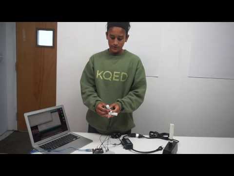
The box close up
The box closed
The box with components
My third modification was pH and Electrical Conductivity sensors and meters. It is important to have these meters because specific plants need specific nutrients (which they usually get in soil) to grow and to become edible. EC and pH are important to measure because different vegetables, fruits, and flowers need different pH and EC measurements. EC measures the quality of the soil and the water in which the plants thrive or don’t grow; it measures the amount of ionic salts in the water supply. pH measures how acidic or basic the soil, water, or plants are. The code for the pH and EC meters are in the main pHbot, but when I tried to test the meters, there were no measurements. I had to add pH and EC code to my hydroBot code. This was a challenge for me because I have never coded before. When I ran into trouble, I had to research for solutions, and I tried my “guess and check” methods. When one method did not work I tried another until I got accurate measurements. I was able to include different EC sensor code into my main HydroBot, but I could not get pH code to work with the rest of the system. I have separate pH code for when I need to measure pH. I will have to upload it to the Arduino before using the sensor. Both sensors are connected to a specific sensor circuit board. They contain ICs (integrated circuits), so they can function as a microprocessor. The sensor sends signals in analog form to the Arduino, so that the Arduino can display the measurements in the serial monitor. I also included a nutrient pump and a temperature sensor in this modification. The nutrient pump is connected to a relay and a 9V battery. The nutrient pump is supposed to be powered by a 12V source, but I did not have any. As a result, the doser pumps the nutrients slower. The doser is a peristaltic pump, and it pumps fluid through flexible tubing by rotating a rotor and pushing the fluid through. The rotor pinches the tubing on one side and forces the fluid to move with the rotor to the other side. The Arduino sends a signal to the relay, and the relay in turn switches the pump on. The code allows for the doser to pump 1mL at a time along with when the water pump is powered on. My final addition was a temperature sensor. It is water proof, so I can test the temperature of the water and the surrounding area. I connected the sensor to a terminal sensor adapter which is attached to the arduino. The termianl sensor adapter has a 10k resistor built in making it a pull up/pull down resistor. It sends temperature signals in digital form to the Arduino, and I coded it so that the Arduino will record Fahrenheit and Celsius.
This is my code with the mods.
#include “DallasTemperature.h”
#include “EEPROM.h”/* I2C interface requirements */
#include “Wire.h”struct DEBOUNCE {
int pin; // number of input pin
int pinState; // the debounced value of input pin
int pinOldState; // previous stable state of input pin
int pinStable; // HIGH if pinState is stable
long lastDebounceTime; // last Reading time
};typedef DEBOUNCE DEBOUNCE_DEF;/* allowcation of 1024 EEPROM */
const byte I2CID = 0;int number = 0;
int state = 0;
double temp;
/* end I2C interface requirements */// Pin assignment
const int flowMeterPin = 2; // water flow meter pin in serial
const int pumpPin = 13; // circulation pump pin out
const int tankLowPin = 7; // water low sensor pin in HIGH means water is Low
const int tankHighPin = 8; // water high sensor pin in LOW means water is Full
const int waterFillPin = 6; // water fill valve pin out
const int ONE_WIRE_BUS = 4; // water temperature pin in
const int phMeterPin = A0;
const int ecMeterPin = A1;
const int supDoserPin = 11;const int NORMAL = 1; // processing state
const int FILLTANK = 2; // processing state
const int FLOWSAMPLERATE = 1000; // 1 second
const int OFF = 0; // device mode
const int ON = 1; // device mode
const int AUTO = 3; // device mode// Setup a oneWire instance to communicate with any OneWire devices
OneWire oneWire(ONE_WIRE_BUS);// Pass our oneWire reference to Dallas Temperature.
DallasTemperature sensors(&oneWire);// Assign the addresses of your 1-Wire temp sensors.
// See the tutorial on how to obtain these addresses:
// http://www.hacktronics.com/Tutorials/arduino-1-wire-address-finder.htmlDeviceAddress waterThermometer = { 0x28, 0xFF, 0xA7, 0xF2, 0x05, 0x00, 0x00, 0x69 };
//DeviceAddress outsideThermometer = { 0x28, 0x6B, 0xDF, 0xDF, 0x02, 0x00, 0x00, 0xC0 };
//DeviceAddress dogHouseThermometer = { 0x28, 0x59, 0xBE, 0xDF, 0x02, 0x00, 0x00, 0x9F };volatile int flowMeterCnt = 10; // measuring the rising edges of the signal
int systemMode = NORMAL; // processing state (NORMAL, FILLTANK)
int pumpMode = AUTO; // pump mode
int pumpState = LOW; // pump current state
int pumpOnTime = 1; // minutes that pump is ON
int pumpOffTime = 2; // minutes that pump is OFF
unsigned long pumpTimer = 0; // clock time when pump state should togglebyte waterFillMode = AUTO; // tank fill valve mode
byte waterFillState = LOW; // tank fill valve current state
unsigned long fillInterval = 60000; // time since last fill one minutebyte waterTempMSB = 80; // thermometer integer full units ie. 93
byte waterTempLSB = 2; // thermometer rounded to one decimal place to the right ie. .2 so together 93.2
byte waterTempTarget = 87;
byte waterTempDelta = 5;
int waterTempSampleRate = 3; // seconds between samples
unsigned long waterTempTimer = 0;unsigned long flowTimer = 0; // clock time when flowMeter should be sampledint supDoserState = LOW; // off
unsigned long supDoserTimer = 0;
byte supDoseMl = 5; // number of ml to dose each timebyte cmdRecieved = 0;
int cmdCnt;
int command;DEBOUNCE_DEF tankLowSensor = { tankLowPin , LOW, LOW, LOW, 0 }; // HIGH = tank empty
DEBOUNCE_DEF tankHighSensor = { tankHighPin , LOW, LOW, LOW, 0 }; // HIGH = tank not fullint sensorValue = 0; // value read from the sensor
float ECcurrent;void setup() {
// initialize serial communications at 9600 bps:
Serial.begin(9600);
/*-(start temperature setup )-*/
/*-( Start up the DallasTemperature library )-*/
sensors.begin();
/*--(end temperature setup)—*/
Serial.begin(9600);pinMode(pumpPin, OUTPUT);
digitalWrite(pumpPin, pumpState); // set initial pump statepinMode(waterFillPin, OUTPUT);
digitalWrite(waterFillPin, waterFillState); // set initial water fill value statepinMode(tankLowPin, INPUT);
digitalWrite(tankLowPin, HIGH); // turn on pullup resistors; open switch state is HIGHpinMode(tankHighPin, INPUT);
digitalWrite(tankHighPin, HIGH); // turn on pullup resistors; open switch state is HIGHpinMode(tankHighPin, INPUT);
digitalWrite(tankHighPin, HIGH); // turn on pullup resistors; open switch state is HIGHpinMode(supDoserPin, OUTPUT);
digitalWrite(supDoserPin, supDoserState); // set initial pump statepinMode(ecMeterPin, OUTPUT);
digitalWrite(ecMeterPin, HIGH);i2cSetup();
oneWireSetup();
// flowSetup();} // setupvoid loop() {sensors.requestTemperatures(); // Send the command to get temperatures
Serial.print(sensors.getTempCByIndex(0));
Serial.println(” Degrees C”);
Serial.print(sensors.getTempFByIndex(0));
Serial.println(” Degrees F”);
delay (15000);
/* end temperature */
/* EC meter */
// read the analog in value:
sensorValue = analogRead(ecMeterPin);
// print the results to the serial monitor:
Serial.print(“ECsensor = ” );
Serial.print(sensorValue);
Serial.print(“\t output = “);
Serial.println(analogRead(1)* 5.00 / 1024, 2);
float CoefficientVolatge;
if(CoefficientVolatge<150)Serial.println(“No solution!”); //25^C 1413us/cmabout 216mv if the voltage(compensate)<150,that is <1ms/cm,out of the range else if(CoefficientVolatge>3300)Serial.println(“Out of the range!”); //>20ms/cm,out of the range
else
{
if(CoefficientVolatge<=448)ECcurrent=6.84*CoefficientVolatge-64.32; //1ms/cm<EC<=3ms/cm
else if(CoefficientVolatge<=1457)ECcurrent=6.98*CoefficientVolatge-127; //3ms/cm<EC<=10ms/cm
else ECcurrent=5.3*CoefficientVolatge+2278; //10ms/cm<EC<20ms/cm ECcurrent/=1000; //convert us/cm to ms/cm Serial.print(ECcurrent,2); //two decimal Serial.println(“ms/cm”); } // wait 30 seconds before the next loop // for the analog-to-digital converter to settle // after the last reading: delay(20000); /* end EC meter */ debouncePin(tankLowSensor); // read tankLow switch debouncePin(tankHighSensor); // read tankHigh switch switch (systemMode) { case NORMAL: normalMode(); break; case FILLTANK: fillTankMode(); break; default: normalMode(); break; } } // loop void normalMode() { if (pumpMode == AUTO) pumpControl(); if (supDoserState == HIGH || supDoseMl > 0) checksupDoser();
/*
if (supDoseMl == 0 && supDoserBtn.pinStable == HIGH && supDoserBtn.pinState == LOW) // pushed manual dose
{
supDoseMl = 3;
checksupDoser();
}
*/
} // normalMode
void checksupDoser()
{
if (supDoseMl > 0)
{
supDoserTimer = setSecondsTimer(supDoseMl); // one milli liter per second
supDoserState = HIGH;
digitalWrite(supDoserPin, supDoserState);
Serial.print(“Doser is “);
Serial.print(supDoserState);
Serial.print(” for “);
Serial.println(supDoseMl);
supDoseMl = 0;
}
if (checkTimer(supDoserTimer) == HIGH) { // timer went off
supDoserState = LOW; // turn doser off
digitalWrite(supDoserPin, supDoserState);
Serial.println(“Doser Off”);
}
}
void checkWaterTemp()
{
if (checkTimer(waterTempTimer) == HIGH) {
getWaterTemp();
waterTempTimer = setSecondsTimer(waterTempSampleRate);
// Serial.print(“sample temp \n”);
}
} //checkWaterTemp
void pumpControl()
{
if (tankLowSensor.pinStable == HIGH && tankLowSensor.pinState == HIGH) { // low water; turn off pump
systemMode = FILLTANK;
pumpState = LOW;
digitalWrite(pumpPin, pumpState);
pumpTimer = millis();
} else { // water in tank
if (checkTimer(pumpTimer) == HIGH) {
pumpState = !pumpState;
if (pumpState == HIGH) Serial.println(“Pump On”);
if (pumpState == LOW) Serial.println(“Pump Off”);
digitalWrite(pumpPin, pumpState);
if (pumpState == HIGH) {
pumpTimer = setMinutesTimer(pumpOnTime);
} else {
pumpTimer = setMinutesTimer(pumpOffTime);
}
}
}
} // pumpControl
void fillTankMode()
{
if (tankHighSensor.pinStable == HIGH && tankHighSensor.pinState == LOW) {
systemMode = NORMAL;
Serial.print(“tank full\n”);
waterFillState = LOW;
digitalWrite(waterFillPin, waterFillState); // turn off water fill valve
} else if (tankLowSensor.pinStable == HIGH && tankLowSensor.pinState == HIGH ) {
waterFillState = HIGH;
digitalWrite(waterFillPin, waterFillState); // turn on water fill valve
Serial.print(“Water low\n”);
} else {
Serial.print(“Filling tank\n”);
}
} // fillTankMode
unsigned long setMinutesTimer(int waitTime)
{
unsigned long endTime;
endTime = millis() + (waitTime * 60000); // convert back to milliseconds from minutes
return endTime;
} // setMinutesTimer
unsigned long setSecondsTimer(int waitTime)
{
unsigned long endTime;
endTime = millis() + (waitTime * 1000); // convert back to milliseconds from seconds
return endTime;
} // setSecondsTimer
int checkTimer(unsigned long timer)
{
if (millis() > timer) {return HIGH;}
else {return LOW;}
} // checkTimer
void debouncePin(DEBOUNCE_DEF& target) {
long debounceDelay = 50; // the debounce time; increase if the output flickers
// read the state of the pin into a local variable:
int reading = digitalRead(target.pin);
// check to see if pin state has changed and you’ve waited
// long enough since the last test to ignore any noise:
if (reading != target.pinState) {
// reset the debouncing timer
target.lastDebounceTime = millis();
target.pinStable = LOW;
if (target.pinOldState == LOW) {target.pinOldState = HIGH;} else {target.pinOldState = LOW;}
}
if ((millis() – target.lastDebounceTime) > debounceDelay) {
// whatever the reading is at, it’s been there for longer
// than the debounce delay, so take it as the actual current state:
target.pinStable = HIGH;
}
target.pinState = reading;
} // debouncePin
/*
Flow meter functions
*/
void flowMeterRpm () //This is the function that the interupt calls
{
flowMeterCnt++; //This function measures the rising and falling edge of the hall effect sensors signal
} // flowMeterRpm
void flowSetup() //
{
pinMode(flowMeterPin, INPUT); //initializes digital pin as an input
attachInterrupt(0, flowMeterRpm, RISING); //and the interrupt is attached
} // flowSetup
void flowMeter()
{
// reading liquid flow rate using Seeeduino and Water Flow Sensor from Seeedstudio.com
// Code adapted by Charles Gantt from PC Fan RPM code written by Crenn @thebestcasescenario.com
// http:/themakersworkbench.com http://thebestcasescenario.com http://seeedstudio.com
int Calc;
if (checkTimer(flowTimer) == HIGH) {// Wait 1 second
cli(); // Disable interrupts
Calc = (flowMeterCnt * 60 / 7.5); // (Pulse frequency x 60) / 7.5Q, = flow rate in L/hour
Serial.print (Calc, DEC); // Prints the number calculated above
Serial.print (” L/hour\r\n”); // Prints “L/hour” and returns a new line
setSecondsTimer(FLOWSAMPLERATE);
flowMeterCnt = 0; // Set NbTops to 0 ready for calculations
sei(); // Enables interrupts
}
} // flowMeter
/*
End Flow Meter Functions
*/
/* IC2 support */
void i2cSetup() {
EEPROM.write(I2CID, 0x8);
// set default i2c ID if not yet defined
// if (EEPROM.read(I2CID)==0) { EEPROM.write(I2CID, 0x4); }
// initialize i2c as slave
Wire.begin(8);
// define callbacks for i2c communication
Wire.onReceive(i2cCommand);
Wire.onRequest(myRequest);
} // i2cSetup
byte i2cResponse[32];
int index = 0;
void myRequest() { // callback for sending data
Wire.write(i2cResponse[index]);
++index;
}
void i2cCommand(int byteCount){ // callback for received data
unsigned char received;
// int cmdCnt;
// int command;
int output;
cmdCnt = Wire.available();
if (cmdCnt > 0 ) {
cmdRecieved++;
command = Wire.read(); // first byte is the command
switch (command)
{
case 1: // set Pump Mode (Off =0, On=1, Auto=3)
if (cmdCnt == 2 ) { // next byte is the mode
pumpMode = Wire.read();
switch (pumpMode) {
case ON: if (tankLowSensor.pinStable == HIGH && tankLowSensor.pinState == LOW) {pumpState = HIGH; } break;
case OFF: pumpState = LOW; break;
}
digitalWrite(pumpPin, pumpState);
Serial.print(“Pump state = “);
Serial.print(pumpState);
Serial.print(“\n”);
}
break;
case 2: // set Pump auto ON time
if (cmdCnt == 3 ) { // next 2 bytes is the time
received = Wire.read();
output = (received << 8); // shift to high byte
received = Wire.read();
output = output + received; // add in low byte
pumpOnTime = output; // ON time in seconds
Serial.print(“Pump auto ON time = “);
Serial.println(pumpOnTime);
}
break;
case 3: // set Pump auto OFF time
if (cmdCnt == 3 ) { // next 2 bytes is the time
received = Wire.read();
output = (received << 8); // shift to high byte
received = Wire.read();
output = output + received; // add in low byte
pumpOnTime = output; // OFF time in seconds
Serial.print(“Pump auto OFF time = “);
Serial.println(pumpOffTime);
}
break;
case 4: // set water Fill Value Mode (Off, On, Auto)
if (cmdCnt == 2 ) { // next byte is the mode
waterFillMode = Wire.read();
switch (waterFillMode) {
case ON: if (tankHighSensor.pinStable == HIGH && tankHighSensor.pinState == HIGH) {waterFillState = HIGH; } break; // only on if not full
case OFF: waterFillState = LOW; break;
case AUTO: if (tankHighSensor.pinStable == HIGH && tankHighSensor.pinState == LOW) {waterFillState = LOW; } break; // turn off if full
}
digitalWrite(waterFillPin, waterFillState);
Serial.print(“water Fill Mode = “);
Serial.println(waterFillMode);
}
break;
case 5: // turn on supDoser for x seconds
if (cmdCnt == 2 ) { // next byte is the number of seconds
supDoseMl = Wire.read();
digitalWrite(supDoserPin, HIGH);
}
break;
case 6: // turn on supDoser
digitalWrite(supDoserPin, HIGH);
break;
case 7: // turn off supDoser
digitalWrite(supDoserPin, LOW);
break;
case 8:
i2cRequest();
index = 0;
break;
default:
Serial.print(“Command not supported “);
Serial.println(command);
break;
} // end switch
} // end if cmdCnt
} // ic2Command
void i2cRequest() { // callback for sending data
byte i2cResponseLen = 0; // response length
unsigned long currentTime = millis();
unsigned long transitionTime = 0;
byte pumpStatus = 0;
byte waterLevel = 0;
byte refillStatus = 0;
byte waterTempSettings = 0;
pumpStatus = (pumpMode << 6) | (pumpState << 5);
if (tankHighSensor.pinState == LOW) { waterLevel = 2; } // Full
else if (tankLowSensor.pinState == HIGH) { waterLevel = 0;} // Low
else { waterLevel = 1;} // Adequate
waterLevel = waterLevel << 3;
refillStatus = (waterFillMode << 1) | waterFillState;
i2cResponse[i2cResponseLen] = pumpStatus | waterLevel | refillStatus;
i2cResponseLen++;
if (currentTime < pumpTimer) {transitionTime = pumpTimer – currentTime;} else {transitionTime = 0;} transitionTime = transitionTime / 60000; // convert to minutes i2cResponse[i2cResponseLen] = (byte)(transitionTime >> 8); // high byte
i2cResponseLen++;
i2cResponse[i2cResponseLen] = (byte)transitionTime; // low byte
i2cResponseLen++;
i2cResponse[i2cResponseLen] = (byte)(pumpOnTime >> 8); // high byte in minutes
i2cResponseLen++;
i2cResponse[i2cResponseLen] = (byte)pumpOnTime; // low byte
i2cResponseLen++;
i2cResponse[i2cResponseLen] = (byte)(pumpOffTime >> 8); // high byte in minutes
i2cResponseLen++;
i2cResponse[i2cResponseLen] = (byte)pumpOffTime; // low byte
i2cResponseLen++;
fillInterval = fillInterval / 60000; // convert to minutes
i2cResponse[i2cResponseLen] = (byte)(fillInterval >> 8); // high byte
i2cResponseLen++;
i2cResponse[i2cResponseLen] = (byte)fillInterval; // low byte
i2cResponseLen++;
i2cResponse[i2cResponseLen] = (byte)(flowMeterCnt >> 8); // high byte
i2cResponseLen++;
i2cResponse[i2cResponseLen] = (byte)flowMeterCnt; // low byte
i2cResponseLen++;
i2cResponse[i2cResponseLen] = (byte)(waterTempMSB); // left of decimal byte
i2cResponseLen++;
i2cResponse[i2cResponseLen] = (byte)(waterTempLSB); // right if decimal byte
i2cResponseLen++;
i2cResponse[i2cResponseLen] = waterTempTarget; // byte
i2cResponseLen++;
i2cResponse[i2cResponseLen] = waterTempDelta; // byte
i2cResponseLen++; // compensate for zero based array 24
/*
Wire.write(i2cResponse, i2cResponseLen);
*/
} // i2cRequest
// end I2C support
// git clone http://github.com/jrowberg/i2cdevlib
// Reads DS18B20 “1-Wire” digital temperature sensors.
// Tutorial: http://www.hacktronics.com/Tutorials/arduino-1-wire-tutorial.html
void oneWireSetup()
{
// Start up the library
sensors.begin();
sensors.setResolution(waterThermometer, 10); // set the resolution to 10 bit (good enough?)
// sensors.setResolution(outsideThermometer, 10);
// sensors.setResolution(dogHouseThermometer, 10);
} // oneWireSetup
float getTemperature(DeviceAddress deviceAddress)
{
float tempF = 0;
float tempC = sensors.getTempC(deviceAddress);
if (tempC == -127.00) {
Serial.print(“Error getting temperature”);
} else {
tempF = DallasTemperature::toFahrenheit(tempC);
Serial.print(“C: “);
Serial.print(tempC);
Serial.print(” F: “);
Serial.print(DallasTemperature::toFahrenheit(tempC));
Serial.print(“\n”);;
}
return tempF;
}
void getWaterTemp()
{
float tempF = 0;
double leftPart;
double rightPart;
double newRight;
sensors.requestTemperatures();
tempF = getTemperature(waterThermometer);
rightPart = modf(tempF, &leftPart);
waterTempMSB = (byte)leftPart;
newRight = rightPart*10;
rightPart = modf(newRight, &leftPart);
waterTempLSB = (byte)leftPart;
} // getWaterTemp
// end DS18B20 support
)
Here is my code in text format
pH code
Here is my code in .zip
Here is the pH code in .zip
Here are the materials I used in this project
These are the libraries I used:
onewire.h
DallasTemperature.h
farmBot.h
Schematic for the pump
Schematic for the pH sensor
Schematic for the EC sensor
MILESTONE THREE
My third milestone is the electrical watering system. The watering system consists of a powerswitch tail, two float switches, a flow meter counter, a submersible pump, and an Arduino uno. To start I wired the flow meter to the Arduino; I wired the signal line to pin 2 and ground to a breadboard that is already wired to the Arduino. The flow meter counter will log and record how much water is flowing out of the tank and into the pex piping. When water is pumped through the pump and into the flow meter counter, kinetic energy is converted into rotational energy by the rotor. The speed of the rotor determines how much liquid is flowing through. The “Hall effect” takes place by electrons being disturbed by a magnetic field. There is an emf due to the magnetic field being perpendicular to the electrical current. There is a hall effect sensor in the flow meter counter that outputs an electrical pulse with every rotation of the rotor.
Next I wired the float switches. The tankLowswitch was wired to pin 7 and the tankHIGHswitch was wired to pin 8. TankLow will control whether the pump is on or not because it will determine the lowest point of water. I placed it right before the pump is exposed to air since the pump needs to be completely submerged in water. The tankHigh will control the highest point of water or when the tank is full and the pump should start pumping. When tankHigh is open but tankLow is closed (the water is between the highest and lowest level), the pump is on and running, but when tankLow is opened as well, the pump turns off and the tank waits until tankLow is closed (until the water rises above the lowest water level). When both are closed (the water is at its highest point), the pump is on and water is pumped through. TankLow can never be open while tankHigh is open since it would mean the water level is low while the level also exceed the highest point. The float switches are normally open, but when they are affected by the water level, they become closed. There is a magnetic reed switch in the float switches that contain two contacts. When the switch rises the magnets come close to the contacts, and make them become attracted to each other. The contacts then complete the circuit and send a signal to the Arduino.
Finally, I wired the powerswitch tail (relay) and the pump. The relay is wired to pin 13 through its +in, and -in is wired to the ground on the breadboard. The code allows the Arduino to control the pump through the relay by the digitalwrite function. Digitalwrite means that the values can only be 0 or 5V, unlike analogwrite which means the values can be a range between 0 and 5. The pump is coded as digitalwrite so it will only be on or off. The pump also runs off 120VAC from an outlet, and the powerswitch relay is plugged into the a wall socket to provide enough voltage.
When I tested the watering system, it worked very well. There were a few leaks, but none to be worried about. The pump was able to pump water all the way up the pex pipe and down through the drip emitters. I used net cups in the plant holes to place the seeds in. When the system ran, the seeds get wet, and some have started to germinate. The water from the return gutters runs fairly well back into the bucket. The original worry was that the water would not run back in, but when enough water is cycling the water flows back in.
A difficulty I encountered during this milestone was the coding. The coding I needed could be found online at Hydroponic farming system. However this coding included the pH sensors and temperature probes so I had to cut all of that code out. I tried to cut out all the pH dosers, One-Wire, and temperature coding. I deleted the libraries not knowing that those are important to the data and code. The libraries store code and manipulate data and are needed for certain commands. I was having trouble getting the I2C data functions to work, but once I researched EEPROM.h and Wire.h I found that they will not work without the correct libraries and coding. After I added those libraries and fixed little problems that I created in the code, it worked well.
I was fortunate to find many schematics online, and the only thing I needed to fix or tweak was the code and adding all the schematics together.
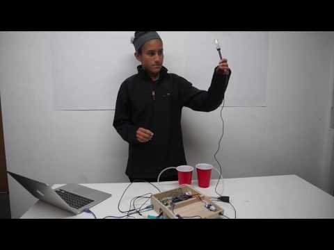
Powerswitch tail and pump
MILESTONE TWO
On the structure there will be 20 grow towers which will support the plants. Each tower has 6 holes for the plants to sit in; the holes are staggered so each grow tower has room to grow the plants. With 20 towers and 6 plant holes, the system can support up to 120 plants at one time. J-hooks hold the vertical grow towers to the top support bars and align them to be under drip emitters. Pex pipes run from the water tank to the top supports and contain the drip emitters, so water can drip into the grow towers and bring nutrients and water to the plants. There are two 48″, one 24″, one 22.4″, and two 25.6″ pex pipes. They will travel up one bottom leg support, fork at the cross section, and continue up to the top supports. The 2 pex pipes that contain the drip emitters were fashioned on the top supports and measure 48 inches long. I marked two holes in the pex starting 4 inches from the ends; after the first marks, the remaining were marked 4.5 inches from each other, giving you 10 spots on the 48 inch pex pipe. The drip emitters were fitted by drilling using a 3/16″ drill bit in to the hole and popping them in. Then I crimped every pex pipe together using copper 3/4 inch rings. The pex pipes are attached to the support frame by zip ties, so I can adjust or repair the pex easily.
The grow towers are PVC gutters that I had cut and molded holes of the plants to sit in. I measured 20 gutters into 48 inches, and I marked lines 6 inches apart starting from the bottom in 10 towers. The other 10 still had marks every 6 inches, but I started at 9 inches from the bottom. Once I drilled them to the J-hooks,

I hung the towers so that the holes would be staggered. I started with the 6 inch from the bottom towers, and in between each I hung the 9 inches from the bottom towers. Each of my grow towers had 6 marks/holes, but one could fit 7. For the plant holes, I cut a 2 inch, horizontal line at every mark. Then I applied heat via a heat gun for 15-20 seconds until the PVC rose towards the heat. Afterwards, the towers could be molded easily using a wooden mold. I used a circular piece of wood that I sanded down so I could slip it into the heated cut in the PVC gutter to create holes that protruded out. I used a 3D printer to print end caps for the pex pipe since I had to seal it so water would not flow out.
The water return gutters, which are located on the bottom cross support, will return the water that drips down the grow towers to the bucket. Potable water tubing, barbed tees, and elbows connect the return gutters to the bucket which are attached to the support bottom by L-brackets and zip ties. I used hose clamps to make sure that the tubing was tight and there would be no leakage. The gutters were also sealed at the ends using gutter end caps and duct tape. PVC glue would work best for sealing the gutters. I also cut a one inch diameter hole in one end cap of each gutter to attach the potable water tubing. I inserted a PVC adapter into the gutter, so I could attach the tubing. Both gutters have tubing, and they are attached to a tee and run back to the tank.
A difficulty I had was working with the pex pipe. The pex was very hard to straighten out, but I cut several 2 feet sections out of 25 feet. Then I ran warm water through the pipe to soften, and not harm, the pieces. I had an easier time molding the softened pipe than trying to straighten out the 25 ft roll it came in. Another difficulty I


faced was managing my time. There are several big mechanical tasks that needed to be done, and at times it seemed nearly impossible to control. This project is mechanically heavy and requires patience to complete. Our engineering notebooks helped me to create daily goals and plan ahead. Instead of worrying about the time limit, I focused on what I could do and worked hard to complete everything I could in a given day.
The tubing was also a challenge to set up. I set up the pump to pump the outgoing water through the pex piping from the bucket. The water return tubing enters the bucket at the highest point where the water will flow out from the gutters and into the bucket. This reduces the amount of water that can be in the bucket, but it also means that the water will circulate more effectively.
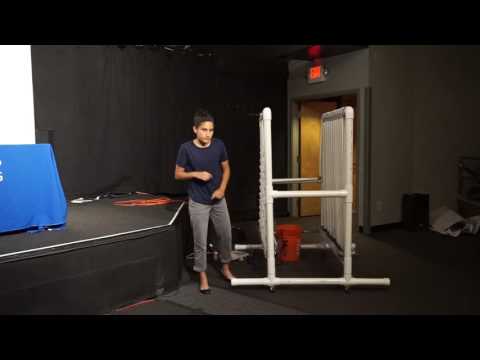
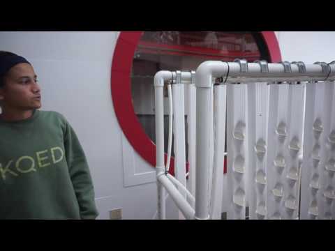
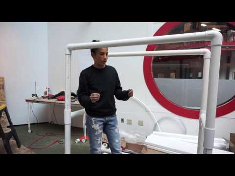
This is my support frame and mechanical water supply sytem
MILESTONE ONE
The support structure is made entirely out of PVC. I kept the original lengths except I reduced the height by 80%, so the height is just over 4 feet instead of over 5 feet. The width and length remain 4 feet. The pipes are all 2 inches in diameter. Cutting the PVC was easy. However, the saw would get caught in the ridges, so I had to cut very slowly. The support frame will hold the grow towers by J hooks attached to the top support legs. The bottom cross support will hold the water return gutters which are under the grow towers. The PVC pipes are connected by tees and elbows. I used 12 tees in total. 4 connected the bottom and foot extensions together, 4 attached the bottom to cross supports, and the last 4 attached the bottom plus cross supports to another cross support. The cross supports also were connected to the leg components. Finally, I used four 90 degree elbows to attach the top support to the leg components. The cross supports ensure that the system is stable and strong enough to hold multiple grow towers with plants and water.
I needed five 10 feet Schedule 40 PVC pipe (2″) for the support frame. I cut down the PVC to have four 48 inch, four 24 inch, four 12 inch, four 22.4 inch, four 25.6 inch, and four 3 inch sections. The 48 inch sections were used for the top support and the lower cross supports. The 22.4 and 25.6 inch sections were used for the vertical leg components. The four 12 inch and two 24 inch sections were used for the support bottom and foot extensions. The last two 24 inch sections were used for the higher cross support. The 3 inch sections were used to connect the support bottom tees to the leg component tees.
HYDROPONICS
Hydroponics is a system which grows plants using nutrients and water without the use of soil. The nutrients can come from a variety of substances including liquid nutrients, manure, and waste. There are several types of hydroponics: vertical, aeroponics, passive sub-irrigation, etc. I am building a vertical hydroponic farming system, and it will be 4’x4’x4′. My system will be small and compact; with 20 grow towers and 6 plant holes in each tower, I will be able to grow up to 120 plants at once. The system is the perfect size for apartments, decks, patios, and small spaces. Even with little space you could have a functional garden! My interest in this project was creating a functional garden that is easy to maintain, build, and grow plants or vegetables from. There could be many environmental advantages from creating a hydroponic system. For example, one could grow their own produce and reduce their carbon footprint. With an increase of plants, more carbon dioxide would be converted to oxygen, and in turn there would be purer air. The watering system would also help one to control and maintain a steady water supply. One could manage the amount of water they are using and reuse water/nutrients more than once.
You can find my project at https://www.hackster.io/bltrobotics/vertical-hydroponic-farm-44fef9?ref=user&ref_id=12499&offset=33 or at http://www.instructables.com/id/Vertical-Hydroponic-Farm/?ALLSTEPS#step11
It was created by Paul Langdon and BLT Robotics.
STARTER PROJECT

The piano is powered by the 2 double A batteries. The LED lights indicate whether the power is on and status of the board. The resistors power and control the correct current to each key so it can be played. The potentiometer selects the octave at which the piano plays; it is a variable resistor and different voltage runs as you turn the knob. The capacitor is a quick-releasing energy source and provides a clean power supply from currents. The microcontroller contains the processor core, memory, and programmable input/output peripherals. Capacitive touch is used to play the notes from the keys. Capacitors consist of two opposite charged plates that store charge. In the keys there is a plate and insulating material. When one’s finger comes into contact with the key, it acts as the opposite plate, dynamically forming a capacitor. This creates a capacitance that can be measured. The resistors send a weak signal, and wires running from the key to the microcontroller determine how hard the key is being pressed. The key must exceed a initial value for the note to be played. The frequency of the key is multiplied by the octave determined by the potentiometer. Each key runs to a different pin in the microcontroller, so different notes play for the different keys. If the button is pressed, a pre-programmed song is played via the microcontroller. There is also a male pin head in case you want to add modifications.
One difficulty I faced was the initial soldering. At times I almost hurt the wires in the board. Another difficulty was figuring out how the piano worked. While resistors do play a major part in the keys, they are not the only requirement. I had to research a lot to find the correct way the piano works. Originally, I was researching the wrong topic, but I kept reading more in depth about the piano to find the mistakes I was looking for. I learned about capacitive sensors and how resistors work alongside of wires or other resistors to send signals to the microcontroller. I also learned that there are a lot of “behind the scenes” events that take place in electrical engineering.
Schematics from http://cdn.sparkfun.com/datasheets/Kits/Gram%20Piano.pdf
Gram Piano