POV LED Cooling Fan Light Display
My project is a cooling fan with several LEDs that spins incredibly quickly and utilizes Persistence-of-Vision to display an image with light. This image is highly customizable, and can range from shapes to text. I also plan on creating a program that allows you to draw your own custom image and have it displayed on the fan.
My Bill Of Materials can be found here.
Engineer
Kevin C.
Area of Interest
Computer Science
School
Homestead High School
Grade
Incoming Junior
Final Milestone
For my second & final milestone I finished piecing together all of the hardware involved in my project while also uploading code and allowing it to properly display text by flashing LEDs. Through this, I learned how to display letters by using arrays, how to remove hot glue from my project, how to solder switches with an arduino and a battery, and how to troubleshoot code.
By connecting all of the resistors with the LEDs, and wiring all of the LED cathodes to the arduino, I created a connection between the LEDs and the arduino, allowing it to be controlled. By placing a flip switch between the circuit created by the lipo battery and the arduino, I allow the switch to complete the circuit, and can turn it on and off. The code I flash onto my arduino allows my LEDs to flash on or off at certain moments based on arrays, creating text when it is spinning.
First Milestone
My main project is the POV LED Cooling Fan Light Display, and for my first milestone I used the CNC to cut out the wooden stick fan used to hold the LEDs, and drilled differently sized holes. After I finished creating my wooden stick, I placed my LEDs on the stick and soldered them together, while also soldering resistors onto my pcb. During my first milestone, I learned how to use Autodesk Fusion 360, make sure that drill holes are accurate, how to use the dremel, and how to use the file. Also, I improved my soldering skills. By soldering the LEDs together, current can pass through and reach all the different LEDs. By adding resistors to the pcb, which will connect to the LEDs with wires, I can also regulate current and make sure that the LEDs are not overloaded. The main challenge I faced was using the CNC, as it took a very long time to prepare. Other challenges I faced were the LEDs not fitting in the holes, which I used the file to fix, drilling the holes with accuracy, and making sure that I didn’t damage the stick with the dremel.
Starter Project
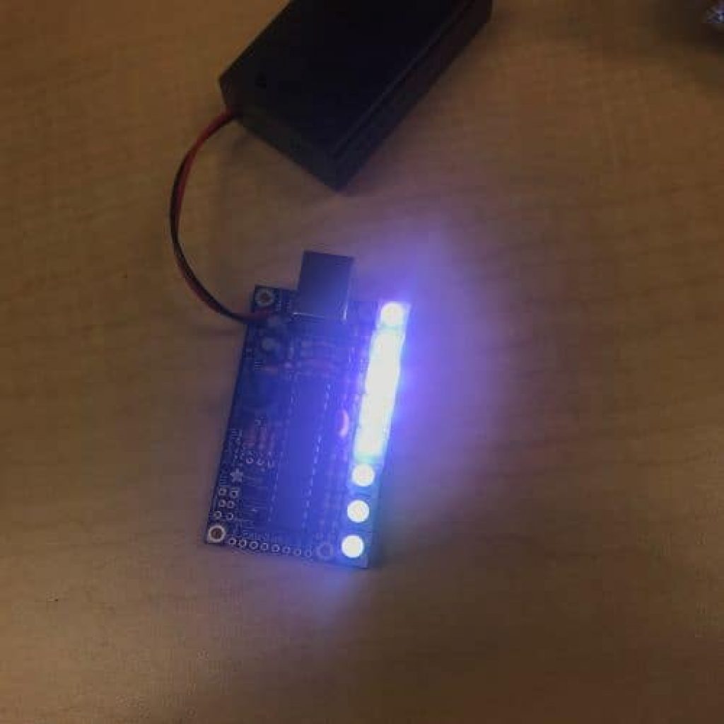
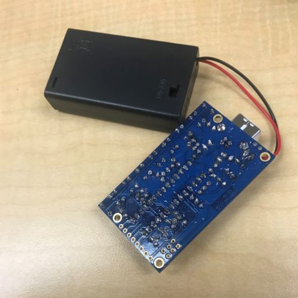

My Starter Project is the Mini POV 4, a fully customizable light painting kit. When you wave the POV in front of a camera on long exposure, it displays an image that appears to be floating. I enjoyed this project because I learned how to properly solder without burning myself (very useful for my main project which involves TONS of soldering) and how the different electrical components work together.
The Mini POV 4 is powered by a 4.5V source (3 AAA batteries). The 100μF capacitors and 0.1μ F ceramic capacitor work together to stabilize the input and output voltage and filter out high and low frequency noise. The potentiometer, the blue object with a dial and an arrow, controls the amount of current that flows to the microcontroller based on the position on the dial. When the dial is turned, the input voltage to the microcontroller is altered, which alters the output (the LEDs’ blinking speed). The 2.2k resistors balance the current flowing to the 3 transistors so that they aren’t overloaded. Because the microcontroller’s signal is not strong enough to communicate with the 8 LEDs, the transistors are used to amplify the signal. Each LED has its own 47 ohm resistor that prevents the LED from overheating. In between the resistors is a ceramic resonator which acts as the board’s metronome and makes sure that the LEDs blink at a consistent rate. The board also has two Zener diodes to make sure electrostatic discharge, when static electricity is released when two objects come into contact, does not occur by making sure that current can only travel in one direction. These Zener diodes are used on the USB interface, ensuring that the data being transferred from a computer to the POV is not interrupted. Finally, there is a USB type B port that allows the user to customize the image shown on the POV by using the Mini POV 4 software on a computer. Users are able to draw their own 8 pixel tall image and download it to their POV.