Resources
Final Milestone
For my final milestone, I placed all the electronics into the speaker box shell. Before doing this, I needed to prep the speaker box shell. To do this, I used wood glue to permanently hold the speaker box shell together. I then used wood screws on the joints of the shell to make the speaker extra secure.
To add the electronics, I soldered wire onto most of the parts and connected the wires with lever nut connectors. With the Arduino and the microphone, I soldered the necessary connections onto a PCB to make it more permanent. To hold the parts in place, I used hot glue to stick the parts to the inner walls of the speaker enclosure.
While doing this milestone, I encountered many challenges. One of them was the front panel not fitting after wood gluing the speaker together. To solve this, an instructor used a belt sander to trim down the edge of the panel to make it fit. Another challenge was wires falling off of the PCB after soldering them. I discovered this was due to using multi-core wire and tinning the wire improperly. Later on, I replaced all most of the multi-core wire connections with solid core wire I found.
Third Milestone
For my third milestone, I made the speaker shell. To do this, I cut and used 3/4 inch thick plywood for the top, bottom, right, and left side of the box. The inner enclosures use 1/2 inch thick plywood. For the front and back panel I used 1/2 inch thick MDF. To cut the wood, an instructor roughly cut out the wood with a jigsaw, which I filed down afterwards. To cut out the speaker holes in the front panels, I used a 3 inch drill bore. The front and back panels back two coats of white spray paint, and all outside-facing pieces have two coats of clear lacquer, sprayed on.
While doing this milestone, a challenge I faced was filing down all the wood. Because of the amount of wood I used and the imperfections of the jigsaw cuts, the amount of filing was both time consuming and tiring. Near the end of the milestone, I ended up using the sanding bit of the Dremel to save time. Another challenge was many gaps of time being unproductive. Because I had to wait for the 3 inch drill bore to arrive and had to wait to use the Dremel, there was a lot of time where I couldn’t progress. To combat this, I started to file minor imperfections in my wood and worked on my website.
The schematics of the wood I cut out is linked here.
Second Milestone
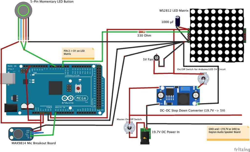
The first part of my second milestone is adding audio reactivity to my RGB matrix. To do this, I wired an electret microphone to the Arduino Mega 2560 in addition to the power supplies mentioned in the last milestone. The VDD of the microphone, which acts as voltage in, is connected to the 3.3V pin of the Arduino, while the ground of the microphone is connected to the ground of the Arduino. In addition to connecting to the 3.3V pin, the VCC pin is also connected to the GAIN pin of the microphone to adjust the microphones gain. The microphone outputs data from the OUT pin to the AI0 (Analog-in pin 0) of the Arduino. The For the RGB matrix, the data-in pin on the RGB matrix was connected to pin 2 of the Arduino. In between pin 2 and the data-in, I added a 330 ohm resistor in between the two to improve the data integrity. I also added a momentary switch that allows me to change the lighting mode of the RGB matrix. The NO (Normally Open) and positive pins of the switch are connected to pin 5, while the COMMON and negative pins are connected to power.
The second part of my second milestone was adding the audio board and speaker drivers to the circuit. I added these before the matrix, meaning that power went to the audio board and speaker drivers before reaching the matrix and Arduino. To do this, I connected 12V power supply to a master switch. The switch splits to the rest of the circuit and to the audio board. To connect the speaker drivers to the audio board, I wired the positive and negative terminals of each driver to the audio board. The master on/off switch is wired like the rest of the buttons in my build. After the switch, the circuit connects to a step-down converter that lowers the voltage to 5V, since that is all the matrix can take. After the converter, I added another latching switch to turn off and on the matrix.
While wiring this part of the circuit, I needed to learn how to wire the speaker drivers to the audio board. However, there was minimal documentation online on how to do this. Because of this, I simply experimented to see which terminal corresponded to which.
The code that I used is linked here.
Electronic wiring diagram

First Milestone
My first milestone is connecting the 16×16 RGB matrix to the Arduino Mega 2560 and power. For power, I used a 12V power supply and stepped the voltage down to 5v using a DC step-down converter, since the RGB matrix can only handle 5V. The Arduino Mega is connected to the matrix through data pin 3 and is running example code from the FastLED library, an Arduino library that allows easy control over RGB LEDs. In addition, it is powered frm the power supply through the VIN (Voltage In) pin. I also used a latching 5v switch in order to easily power on and off the RGB Matrix. The COMMON and negative pins of the switch are wired to the power source, while the NO (Normally Open) and positive pins are wired to the RGB Matrix. The COMMON and negative pins light the LED on the switch itself, while the NO and positive pins complete the circuit. To connect all the pins of the circuit, I learned how to use a breadboard and utilized it. While doing my first milestone, I learned the importance of having a common ground in my circuit. When I made the circuit without common ground, the matrix started to glitch out. However, after adding it, it started to function properly.
The example code that I used is linked here.
Starter Project
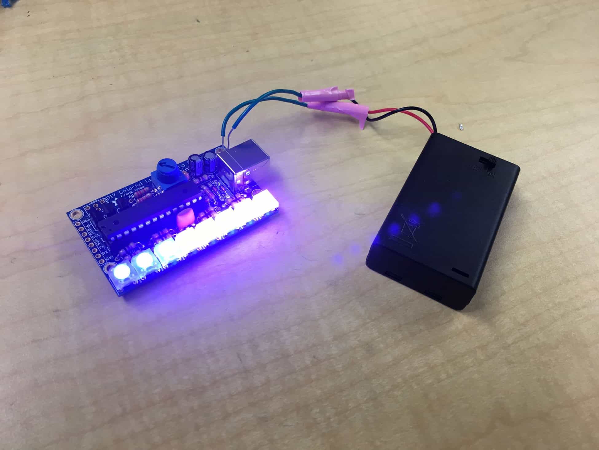
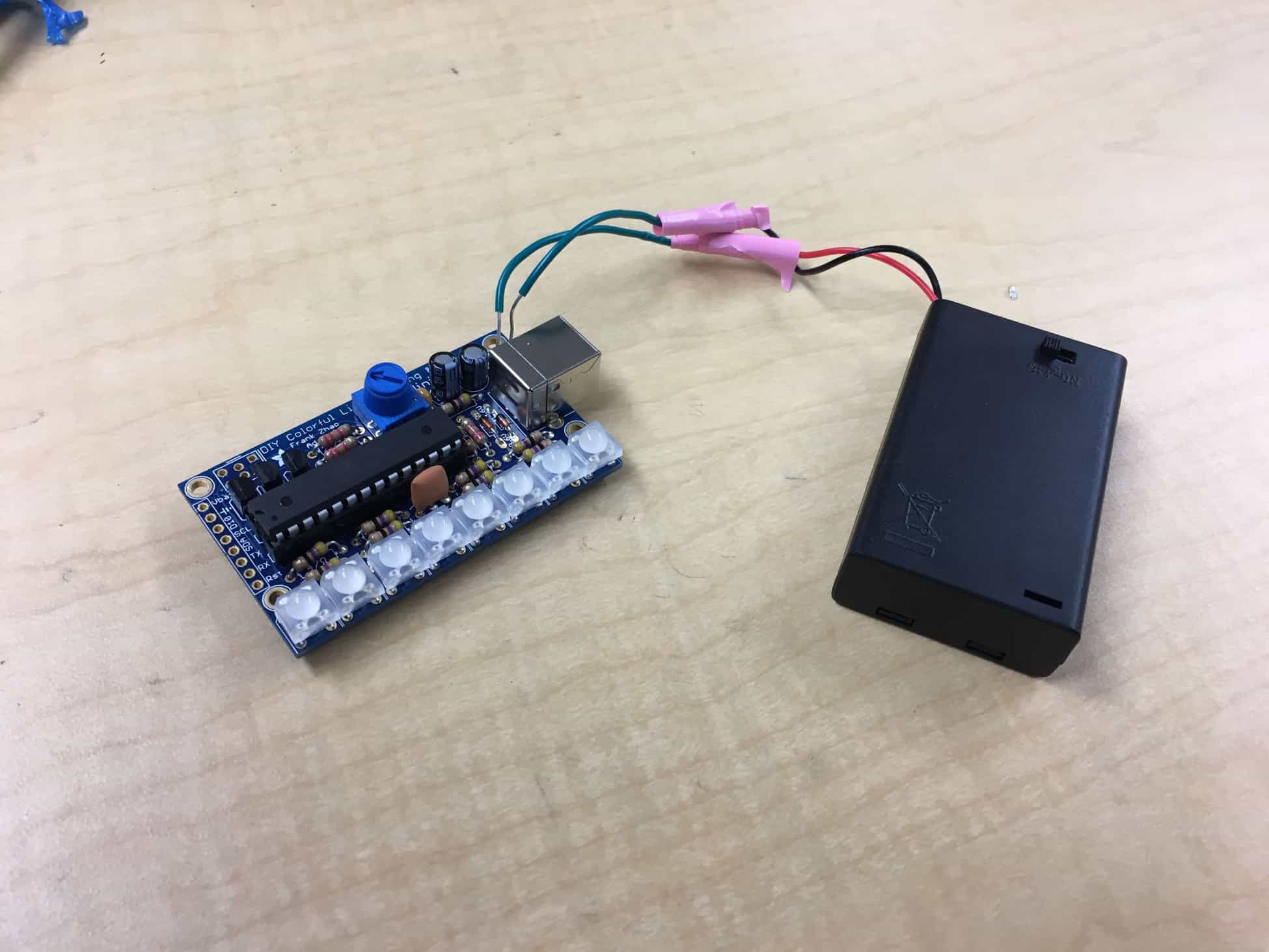
My starter project is the Mini POV. The Mini POV is a device that, when waved in the air, creates an image using 8 RGB leds. To create the image, the device momentarily flashes the colors of each column of the image. By quickly flashing all columns of the image, it creates the entire image by dragging the Mini POV through the air.
The device is controlled by an Atmega328P-PU, powered by 3 AAA batteries, and contains a USB-B port to add custom images to display. The Mini POV also contains a potentiometer, which controls the speed of the flashing to change the length of the image, a crystal oscillator to serve as an internal clock, transistors to amplify the current, resistors to limit the current, and capacitors to store current.
While making the Mini POV, I learned how to solder and de-solder and the importance of strengthening weak wires. When I first completed my project, the battery leads broke off due to the wire being weak, which resulted in me taking a considerable amount of time to reinforce and reattach the leads.


