Lunar Phase Clock
A clock with a lamp that simulates the moon phase according to time and date. An OLED screen displays the time, temperature, and humidity.
Engineer
Kenneth M.
Area of Interest
Electrical Engineering
Mechanical Engineering
School
Gunn High School
Grade
Incoming Sophomore
Reflection
My experience at Blustamp engineering has been very positive, as it allowed me to build something on my own and have fun while doing it. It also gave me a chance to experience engineering, something I had always been interested in.
My favorite memory at BlueStamp has been when the moon stopped flashing rapidly and finally lit up properly after about a week of struggle to correct the code. It is always exciting to see something working, especially when it’s the result of days of hard work.
The next step in this project is allowing it to communicate with other devices via WiFi or bluetooth. Adding a WiFi module would allow the user to control the light with their smartphone or Alexa.
Blustamp has taught me a lot and helped me grow. I learned best practices for soldering, connecting wires on a breadboard, and programming for the Arduino. I enjoy all of the things I have learned at BlueStamp, and I will certainly keep exploring engineering and computer science in the future. For example, I am taking an engineering class at my school to enhance my knowledge.
Demo Night
Successful Demo
Note: The clock did not work during the initial presentation. The video above shows the successful demo.
Presentation
Final Milestone
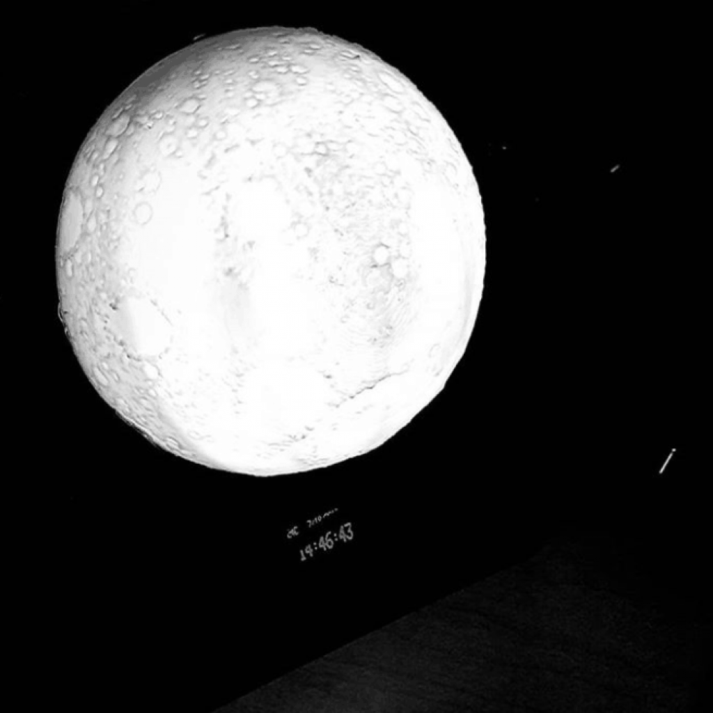
My final milestone is completing the lunar phase clock and allowing it to synchronize with the lunar phase in the real world. The clock also features an OLED screen to show the current time, temperature, and humidity. A real time clock in the back enables time-keeping even without power supply.
In order to show the current moon phase, the Arduino Nano takes the current date from the real time clock, then plugs the year, month, and date into a function. This function calculates a phase number and lights up the LEDs according to the value. The data from the temperature and humidity sensor is also sent to the Arduino and then to the display.
When I was working on reaching the final milestone, I encountered the problem of the moon not properly lighting up. Instead, all of the lights are always on and flash extremely rapidly. To fix this problem, I had to replace the code I downloaded from instructables with new code that I wrote. This solved the issue and the moon now lights up properly.
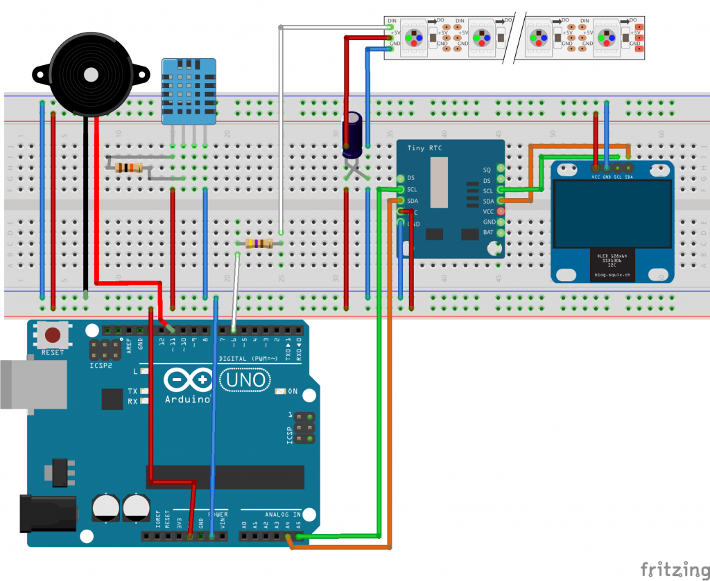
Neopixel: 470Ω DHT11: 10KΩ 1000μF, 6.3V Capacitor

Second Milestone
My second milestone is fixing the LED light strip into the moon and letting the moon light up. Its color, brightness, and pattern can be controlled by the Arduino.
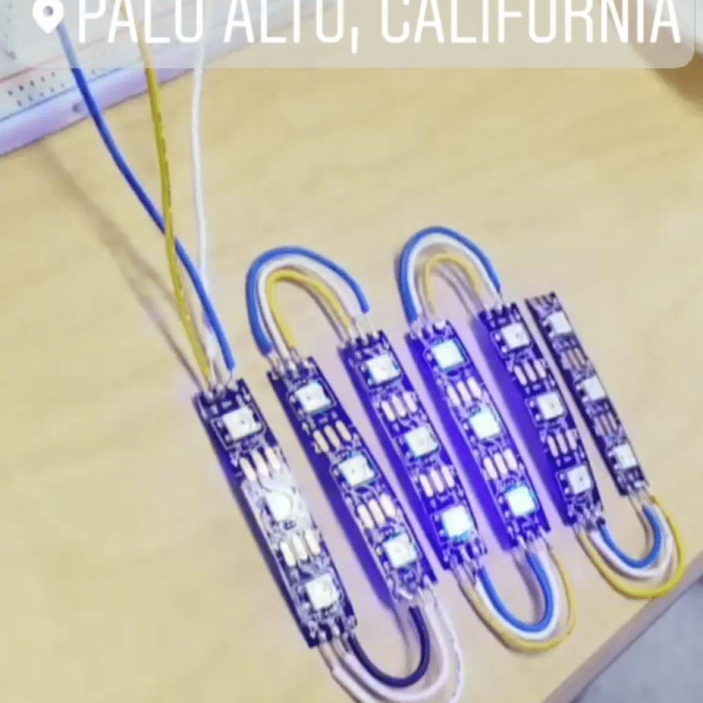
To fix the LED strip into the light fixture, I had to cut my NeoPixel strip into portions of 3 LEDs, then connect them by soldering wires onto each strip. This was challenging as each strip was narrow and the soldering pads were small. When I first finished soldering the strips, the moon lit up for a few minutes, then malfunctioned. This was due to the first strip being broken from repeated soldering. I fixed the problem by replacing the first strip with a new one and placing hot glue on the solder joints to secure them. The moon is now stable and not prone to breakage.
The test code I used was from Adafruit, with a few pixels lighting up in succession down the length of the strip, to verify that all connections are working.
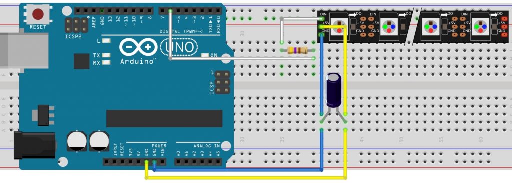
470Ω Resistor 1000μF, 6.3V Capacitor
First Milestone
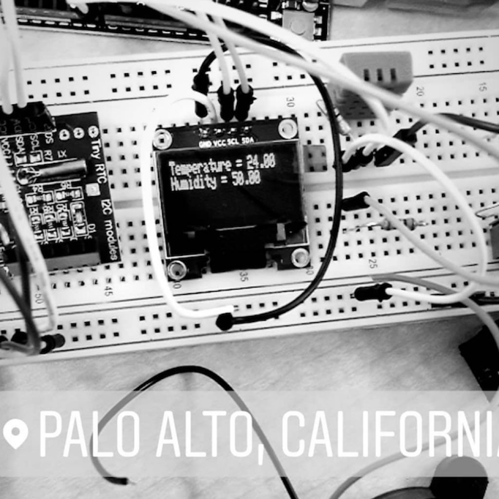
My first milestone is displaying the current temperature and humidity on an OLED screen. This requires the OLED screen and the temperature/humidity sensor to be connected to the Arduino. By making an OLED weather station, I can test if the screen is displaying things properly and if the temperature/ humidity sensor is outputting correct values.
For the Arduino to receive data from the temperature/humidity sensor and show it on the screen, I used code from the test program for the DHT11 temperature/humidity sensor, and code from the Adafruit example program for the SSD1306 OLED display.
When I was working on this milestone, I faced the problem of the screen not lighting up. It only worked for about every other attempt. This problem was caused by using a power bank as the power supply. It turned itself off because it couldn’t detect the request from the screen and the sensor for power. By switching to the Arduino’s built-in 5v pin as the power supply, power can be given to the OLED screen and the sensor consistently and reliably.
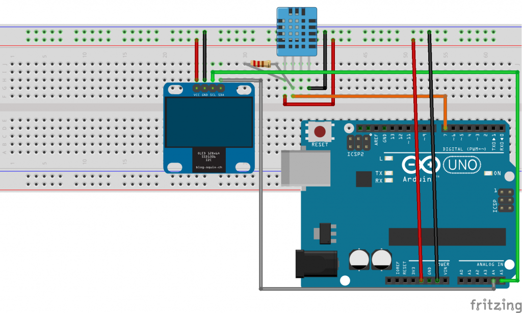
10KΩ Resistor
Starter Project
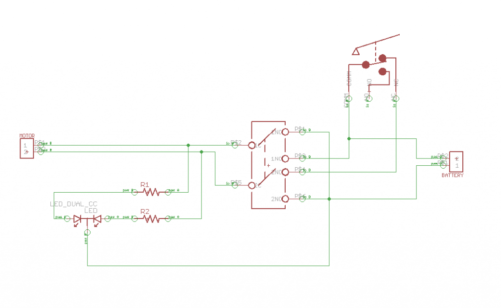
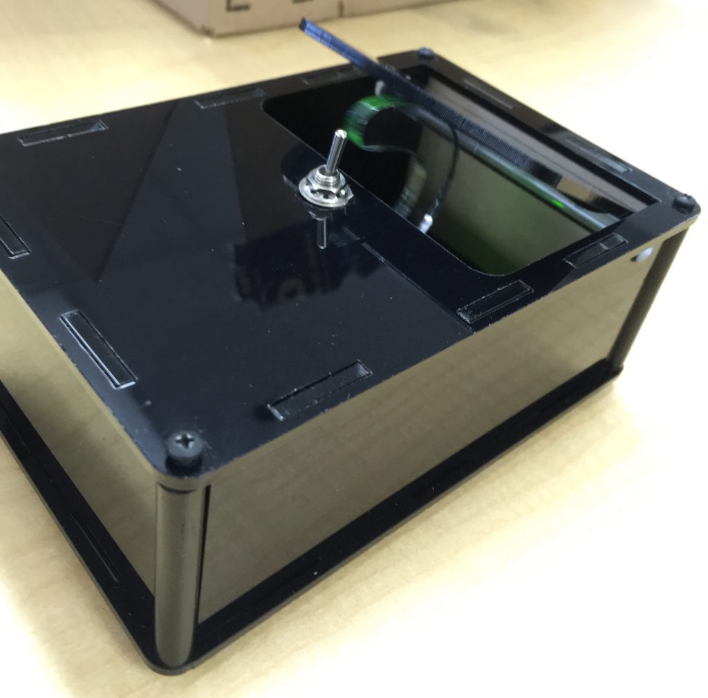
My Starter Project is the Useless Machine, which turns itself off whenever it is turned on.
When the switch on top of the box is turned on. Current flows from the batteries to the resistors, which lower. It then goes to the motor and the LED. The motor starts to spin and the LED glows green. The arm attached to the motor flips the switch back to the off position, and this causes the motor to turn backwards. The color of the LED changes to red. As the arm pushes a snap switch inside the box, the current stops flowing. The motor stops spinning and the LED turns off.
When I tested the machine after soldering, I encountered a problem that the motor does not spin and the LED fails to light up. The problem seemed to be the soldering, according to a multimeter. The solder of the switch did not connect to the PCB, which made the switch fail to function. After I fixed the soldering, both the motor and the LED worked.
pretty good 😉