
Gesture Control Robot
The Gesture Control car is a Robotic car that takes data from the gestures I make with hand and interpret these gestures as commands to move the robotic car is different directions. The Car also has a second mode known as autonomous mode where it can move on it own without receiving data from the accelerometer on my hand.
Engineer
Kelvin N
Area of Interest
Mechanical/ Environmental Engineering
School
Bronx Envision Academy
Grade
Incoming Senior
Fifth Milestone
During my fifth milestone I worked on adding a push button that would allow my car to switch to autonomous mode when pressed . Finding a diagram that would allow me to connect the button to the Arduino was a little challenging, most of the diagrams I came across was made specifically to turn on an LED, the LED was connected using a lot of different wires that I did not need to make just a push button; after researching I was able to find a diagram which would allow me to switch to autonomous mode when pressed. The diagram I provided shows how I was able to connect the button to the Arduino.
After I wired up the button, I worked on writing a code that allow the Arduino to switch modes when pressed, the code itself was simple; the code works by making the car move back and turn right whenever it came in contact with an object.The ultrasonic sensor I added on the previous milestone allowed me to add this feature.The led lights also works the same in autonomous mode and gesture control mode.
Button wiring diagram

Fourth Milestone
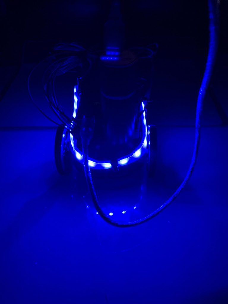
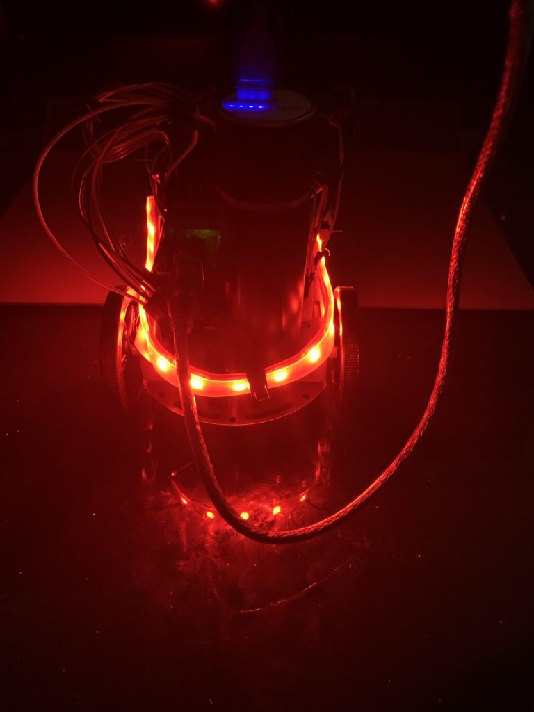
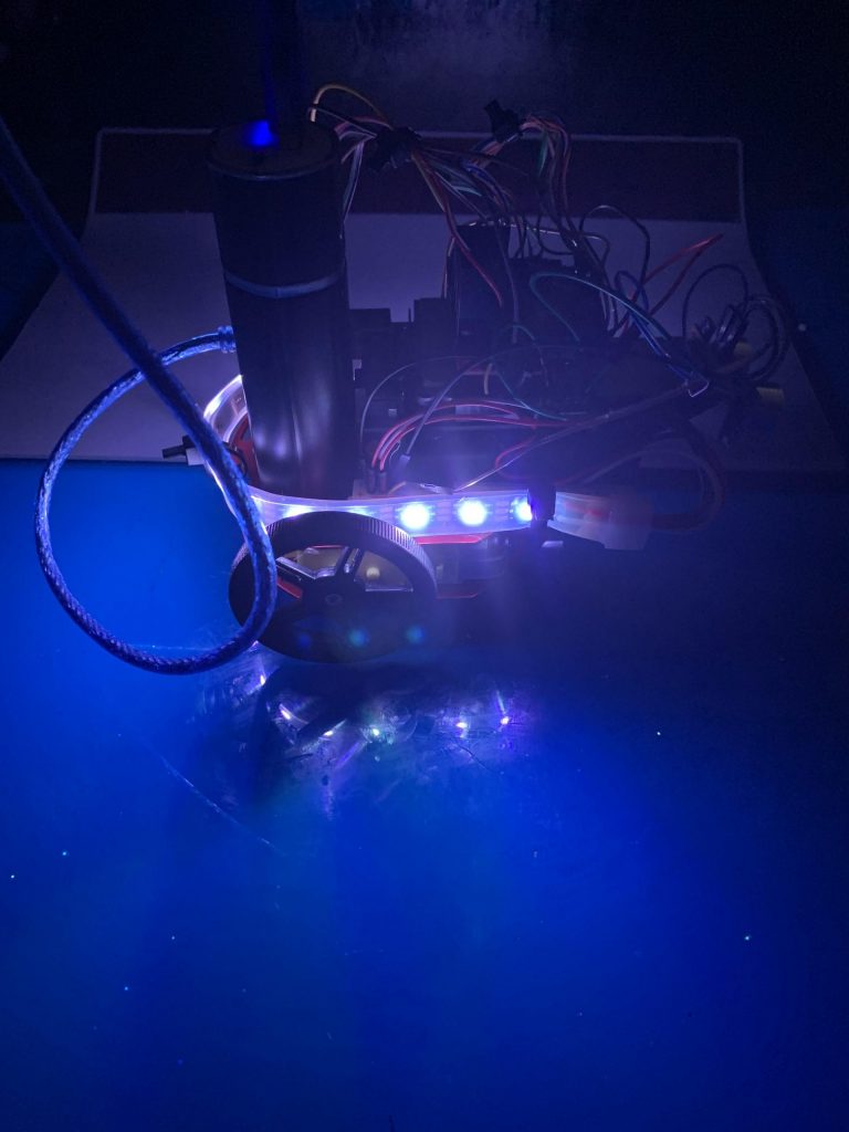
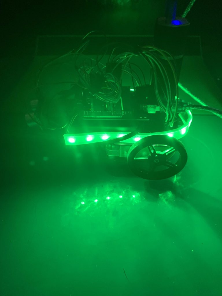
I acomplished my fourth milestone on July 30th 2020, on this milestone i worked on adding LEDs to my car to signal the direction my car is going and also to provide visibility in the dark. The LED strip came with 60 LEDs on it , this was much longer than i needed, so i cut it and used 17 LEDs that were able to fit on my car.
Adding the LED attachment reveled a problem that would prevent me from adding future modification. The problem regarded finding GND And Power Pins to connect new attachments to the car, since all of the said pins were being used. After consulting with my instructor i figured out a way to create new GND and Power pins for the micro controller; I would be using a bread board to create new pins. I connected the bread board by unplugging two wires that were connected to GND and 5v; after unplugging the wire I connected jumper wires from the power and ground of the bread board to the 5v and GND of the micro controller.Being able to connect the bread board allowed me to connect the previous wires i had unplugged and also new wires such the GND and Power wires of the LED strip.
Different light in accordance with the direction of the car.
Third Milestone
During my third milestone i worked adding an ultrasonic sensor to the car, the sensor would allow the car to avoid objects when being controlled by me; the ultrasonic sensor has four pinouts( VCC, Trig, Echo , GND).
In order to connect the VCC and and GND pins I needed to create new power and ground pins, since the all the power and ground pins on my Arduino were being used, i got around this problem by using a breadboard I disconnected two wires that were using the GND and Power pins and used a jumper wire to connect the GND and Power to the breadboard. After creating new pins for Power and Ground, i connected the VCC and GND to the the breadboard. The Echo pin(output) and the Trig pin(Input) sent and receive sound waves in order to calculate distance .
Next I worked on adding a code that would allow my car to move back whenever it came it in contact with an object. The code works by having the ultrasonic sensor detect when an object is nearby, and when the sensor locates an object it emit sound waves ;when the sound waves are reflected back to the sensor it calculates the distant using the time it took for the sound waves to be reflected , i have implemented a code that tells the car to move back when the ultrasonic sensor reads a specific distance.
Ultra sonic sensor on car

Second Milestone
During my Second Milestone i worked on constructing the body of my car, Sewing my remote unit onto a glove and Uploading a code to control the car with the remote unit.
The car came with two motors and wires already soldered onto it, but the wire disconnected ,so i had to use a soldering iron and solder to connect the wires back onto the motor. My next step was to connect the wires of the motors to the motor driver,the motor drive had OUTPUTS 1 & 2, where the wires of motor A would be connected and OUTPUTS 2 & 4 where Motor 2 B would be connected.
Next I worked on connecting the Arduino Uno to the motor driver;The Arduino would control the speed and direction the car takes. Pins IN1 & IN2 on the motor driver would control the spinning direction of motor A, while pins IN3 & IN4 control the spinning direction of motor B, I then added the battery that would provided power for the motor driver.
After I completed working on the car, I moved to work with the accelerometer, the accelerometer is the device that would take gestures from my hand and interpurate them into readable values that the Arduino uno can turn into commands to move the car. The data is sent over radio frequency through the two NFRs on the Arduino Nano and Arduino Nano . I began working with the accelerometer by soldering the pins that would help me connect the accelerometer with the Arduino Nano. Soldering was a new skill that I had to learn to get my accelerometer working, i learned how to solder by soldering multiple resistors to a perf board , and after being confident in my soldering I soldered the the pins and connected the accelerometer to the Arduino Nano . I connected the accelerometer to the Arduino using 12c communication, this allows to use two lines (SCL and SDA) on the arduino Nano to send and receive data; the power pins (VCC and GND) were connected to the 3.3v and GND on the Arduino Nano.
After completing the connection between the Arduino Nano and Uno, it was time to sew my components into the glove , After sewing I uploaded a code to move the car, the code works by collecting data with the accelerometer, and sending it to the car to make it move in different directions. The code had challenges that took up the majority of my time during milestone 2, the code i uploaded could not be read by the Arduino Nano on the car , so i tried running a “Hello World” code to test if all my wiring was correct, after encountering the same problem again i decided to switch my wires that were connected to the Arduino Uno. Switch the wires allowed the Arduino to read the code and i was able to move my car with the Remote Glove.
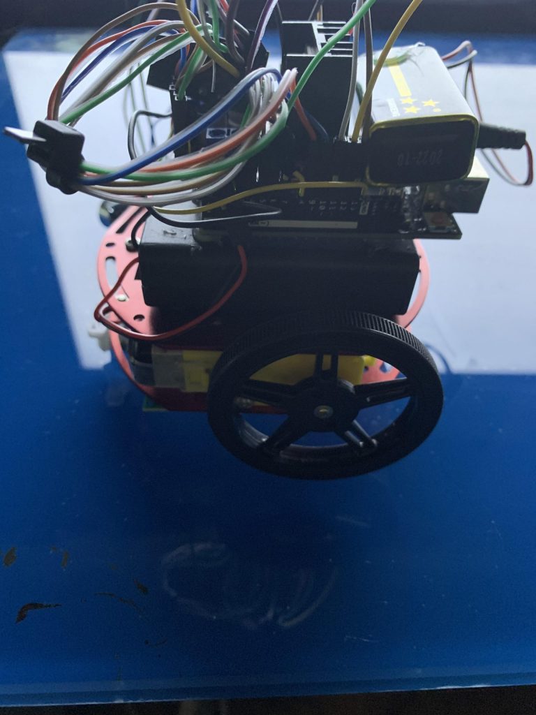
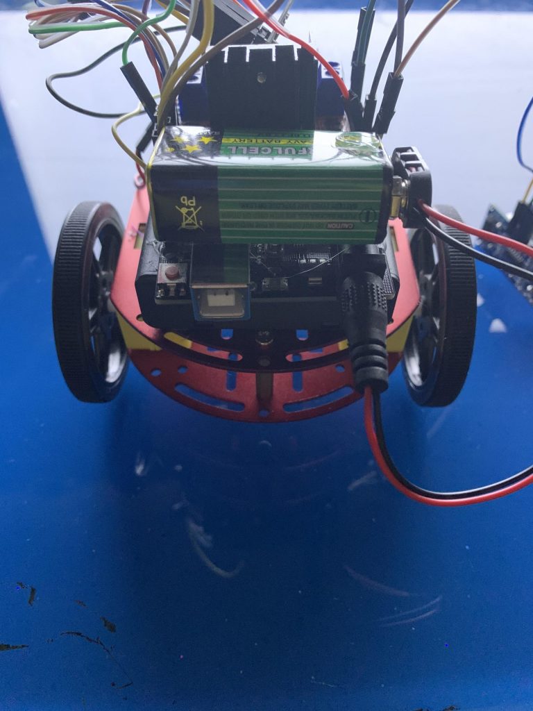
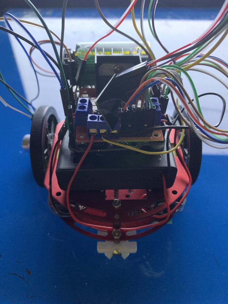
Receiver Car
Transmitter Glove

#include <SPI.h>
#include <nRF24L01.h>
#include <RF24.h>
#include <Adafruit_MPU6050.h>
#include <Adafruit_Sensor.h>
#include <Wire.h>
int command = -1;//0=foward
//1=backwards
//2=right
//3=left
RF24 radio(7, 8); // CE, CSN
const byte address[6] = “00001”;
Adafruit_MPU6050 mpu;
void setup() {
Serial.begin(115200);
while (!Serial)
delay(10); // will pause Zero, Leonardo, etc until serial console opens
Serial.println(“Adafruit MPU6050 test!”);
// Try to initialize!
if (!mpu.begin()) {
Serial.println(“Failed to find MPU6050 chip”);
while (1) {
delay(10);
}
}
Serial.println(“MPU6050 Found!”);
radio.begin();
radio.openWritingPipe(address);
radio.setPALevel(RF24_PA_MIN);
radio.stopListening();
mpu.setAccelerometerRange(MPU6050_RANGE_8_G);
Serial.print(“Accelerometer range set to: “);
switch (mpu.getAccelerometerRange()) {
case MPU6050_RANGE_2_G:
Serial.println(“+-2G”);
break;
case MPU6050_RANGE_4_G:
Serial.println(“+-4G”);
break;
case MPU6050_RANGE_8_G:
Serial.println(“+-8G”);
break;
case MPU6050_RANGE_16_G:
Serial.println(“+-16G”);
break;
}
mpu.setGyroRange(MPU6050_RANGE_500_DEG);
Serial.print(“Gyro range set to: “);
switch (mpu.getGyroRange()) {
case MPU6050_RANGE_250_DEG:
Serial.println(“+- 250 deg/s”);
break;
case MPU6050_RANGE_500_DEG:
Serial.println(“+- 500 deg/s”);
break;
case MPU6050_RANGE_1000_DEG:
Serial.println(“+- 1000 deg/s”);
break;
case MPU6050_RANGE_2000_DEG:
Serial.println(“+- 2000 deg/s”);
break;
}
mpu.setFilterBandwidth(MPU6050_BAND_21_HZ);
Serial.print(“Filter bandwidth set to: “);
switch (mpu.getFilterBandwidth()) {
case MPU6050_BAND_260_HZ:
Serial.println(“260 Hz”);
break;
case MPU6050_BAND_184_HZ:
Serial.println(“184 Hz”);
break;
case MPU6050_BAND_94_HZ:
Serial.println(“94 Hz”);
break;
case MPU6050_BAND_44_HZ:
Serial.println(“44 Hz”);
break;
case MPU6050_BAND_21_HZ:
Serial.println(“21 Hz”);
break;
case MPU6050_BAND_10_HZ:
Serial.println(“10 Hz”);
break;
case MPU6050_BAND_5_HZ:
Serial.println(“5 Hz”);
break;
}
Serial.println(“”);
delay(100);
}
void loop() {
sensors_event_t a, g, temp;
mpu.getEvent(&a, &g, &temp);
Serial.print(a.acceleration.x);
Serial.print(” “);
Serial.println(a.acceleration.y);
delay(250);
if (a.acceleration.x < -3) {
command = 2;
Serial.println(command);
radio.write(&command, sizeof(command));
}
else if (a.acceleration.x > 3) {
command = 3;
Serial.println(command);
radio.write(&command, sizeof(command));
}
else if (a.acceleration.y < -3) {
command = 0;
Serial.println(command);
radio.write(&command, sizeof(command));
}
else if (a.acceleration.y > 3) {
command = 1;
Serial.println(command);
radio.write(&command, sizeof(command));
}
else if (-3 < a.acceleration.y && a.acceleration.x < 3) {
command = 4;
Serial.println(command);
radio.write(&command, sizeof(command));
}
}
#include <SPI.h>
#include <nRF24L01.h>
#include <RF24.h>
#include <Adafruit_MPU6050.h>
#include <Adafruit_Sensor.h>
#include <Wire.h>
#include <L298N.h>
const unsigned int IN1 = 10;
const unsigned int IN2 = 6;
const unsigned int ENA = 9;
const unsigned int IN3 = 5;
const unsigned int IN4 = 4;
const unsigned int ENB = 3;
RF24 radio(7, 8); // CE, CSN
int value = -1;
const byte address[6] = "00001";
Adafruit_MPU6050 mpu;
const int trigPin = A4;
const int echoPin = A5;
// defines variables
long duration;
int distance;
void setup() {
Serial.begin(9600);
radio.begin();
radio.openReadingPipe(0, address);
radio.setPALevel(RF24_PA_MIN);
radio.startListening();
pinMode (IN1, OUTPUT);
pinMode (IN2, OUTPUT);
pinMode (IN3, OUTPUT);
pinMode (IN4, OUTPUT);
pinMode (ENA, OUTPUT);
pinMode (ENB, OUTPUT);
delay(100);
pinMode(trigPin, OUTPUT); // Sets the trigPin as an Output
pinMode(echoPin, INPUT); // Sets the echoPin as an Input
Serial.begin(9600); // Starts the serial
}
void loop() {
if (radio.available()) {
radio.read(&value, sizeof(value));
Serial.println(value);
if (value == 3) {
//Serial.print(text);
analogWrite(ENA, 80);
analogWrite(ENB, 70);
digitalWrite(IN1, HIGH);
digitalWrite(IN2, LOW);
digitalWrite(IN3, LOW);
digitalWrite(IN4, HIGH);
}
else if (value == 2) {
analogWrite(ENA, 80);
analogWrite(ENB, 70);
digitalWrite(IN1, LOW);
digitalWrite(IN2, HIGH);
digitalWrite(IN3, HIGH);
digitalWrite(IN4, LOW);
}
else if (value == 1) {
analogWrite(ENA, 90);
analogWrite(ENB, 90);
digitalWrite(IN1, LOW);
digitalWrite(IN2, HIGH);
digitalWrite(IN3, LOW);
digitalWrite(IN4, HIGH);
}
else if (value == 0) {
analogWrite(ENA, 90);
analogWrite(ENB, 90);
digitalWrite(IN1, HIGH);
digitalWrite(IN2, LOW);
digitalWrite(IN3, HIGH);
digitalWrite(IN4, LOW);
}
else if (value == 4) {
analogWrite(ENA, 0);
analogWrite(ENB, 0);
digitalWrite(IN1, LOW);
digitalWrite(IN2, LOW);
digitalWrite(IN3, LOW);
digitalWrite(IN4, LOW);
}
else {
analogWrite(ENA, 0);
analogWrite(ENB, 0);
digitalWrite(IN1, LOW);
digitalWrite(IN2, LOW);
digitalWrite(IN3, LOW);
digitalWrite(IN4, LOW);
//digitalWrite(10, LOW);
delay(1000);
}
}
}
First Milestone
My First Milestone for the Gesture Control Car is to have the two NRF24L01’s to communicate with each other;the NRF24L01 allows for wireless communication between two devices. Data is sent between the receiver and transmitter module. The NRF will send radio waves to other NRF with the same address; On the NRF24L01 there are different pins with specific functions, the CSN and CE acts as the transmitter and receiver pins, they allow me to set one NRF as receiver and the other as transmitter, the SPI Pins( SCK,MOSI and MISO) on the the NRF is connected to the SPI pins on the Arduino, these pins allow for communication between the arduino and the NRF, which in turn enables me to send a code to the NRF . The NRF on the nano acts as the transmitter that sends data to the receiver NFR on the Arduino Uno. I uploaded a code to the Nano that sends a “ Gesture Control Robot” message to the arduino uno.


#include <SPI.h>
#include <nRF24L01.h>
#include <RF24.h>
RF24 radio(7, 8); // CE, CSN
const byte address[6] = "00001";
void setup() {
Serial.begin(9600);
radio.begin();
radio.openReadingPipe(0, address);
radio.setPALevel(RF24_PA_MIN);
radio.startListening();
}
void loop() {
if (radio.available()) {
char text[32] = "";
radio.read(&text, sizeof(text));
Serial.println(text);
}
}
#include <SPI.h>
#include <nRF24L01.h>
#include <RF24.h>
RF24 radio(7, 8); // CE, CSN
const byte address[6] = "00001";
void setup() {
radio.begin();
radio.openWritingPipe(address);
radio.setPALevel(RF24_PA_MIN);
radio.stopListening();
}
void loop() {
const char text[] = "Gesture Control Car";
radio.write(&text, sizeof(text));
delay(1000);
}