
Hello World!
My name is Kelly and I go to New Explorations into Science Technology and Math. My starter is the Crawling Microbug and my main project is the Portable Sun Tracking Solar Panel with a Windup Clock Drive.

Portable Sun Tracking Solar Panel With A Windup Clock Drive
From my previous post, I have added a switch to my solar panel. This switch allows me control whether I want my solar panel to charge my battery or turn on some LED. I was not going to add this the first time, but I needed to know if my solar panel had current going through it. So the simplest way to figure that out was with a LED. With that complete, my project now has some electrical engineering in it… well kind of, yay!
I found this project on…
http://www.instructables.com/id/Portable-Sun-Tracking-Solar-Panel-With-A-Windup-Cl/
The materials I have used…
Main Project Milestone #3!! (July 25,2013)
Hello World!
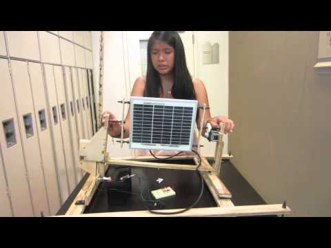
Portable Sun Tracking Solar Panel With A Windup Clock Drive is complete! I have placed the “U” bracket on top of the base, right between the two rods.
The “U” bracket was not stable so I drilled a piece of threaded rod through the small rod and the right side of the “U” bracket (the opposite side where the clock drive is placed). Addition to that I needed to add two sort of triangle pieces on the left side of the “U” bracket so I could do the moving/ sliding mechanism.

The gears mesh correctly and the whole solar panel rotates with the help of the roller bearings that are inserted inside the wood.

I winded up the clock drive and let it run overnight to test out whether the solar panel will actually rotate and sure enough the next day the solar panel had rotated.
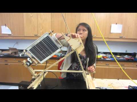
The sliding mechanism is what is going to allow the solar panel to move up and down the long rod at an angle between 0 and 90 degrees. The friction wedge, which is what holds up the solar panel, needed to have three holes drilled inside of it aligned to the two triangles connected to the “U” bracket. I placed a piece of sand paper on the friction wedge and the long rod so that the solar panel would not slid right back down and stay up for as long as you winded up the clock drive.
I am now working on adding a switch that will allow me to control whether I want the solar panel to charge my 12 V sealed rechargeable lead battery or a board of LED’s.
*I do not know what’s wrong with the font in the beginning, sorry about that!
Main Project Milestone #2! (July 15, 2013)
Hello World!
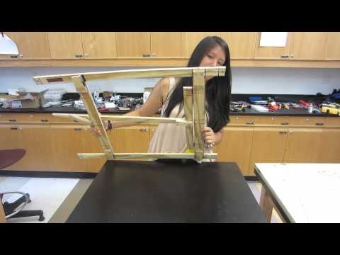
My second milestone is the completion of the base for my solar panel. The base is important because it holds up the solar panel and it must sturdy because the solar panel will be rotating, even if it is going to go at a really slow pace.
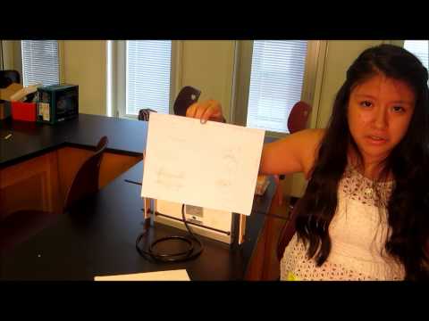
Mechanical Drawing of Base:

After that I drew all of the dimensions on a large piece of wood so I can hand it to Kyle (He has access to a wood shop). When he gave me the pieces of wood back I started creating the base.
The Under Part of the Base:
![photo_1[1]](http://bluestampengineering.com/wp-content/uploads/photo_11.jpg)
I had to place blocks of wood on each corner because the screws were not sturdy enough and it would spin. The blocks kept it really sturdy and it is strong enough to hold up the solar panel now.
Top Part Of The Base:

Main Project Milestone (July 05,2013)
Hello World!
One milestone that I have completed for my main project is my “Wooden” Frame. It was not as hard as I expected it to be to complete. The website that this project comes from had very small information and directions to create this so I had to start from scratch. I created some mechanical drawings based on the solar panel that was already purchased.
Mechanical Drawing of “Wooden” Frame:

After I finished my mechanical drawings with all of the dimensions, I started to bring it alive. I had to drill two holes on the sides of my solar panel so I could put through the threaded rod. The threaded rod is for keeping the solar panel steady. I placed 14.5” of threaded rod through the solar panel and then I had to saw two pieces of wood to keep them balanced and together. Both pieces of wood are 9” long and have three drilled holes in them. The third hole is in the middle and it is for another piece of threaded rod that allows the solar panel to rotate. One roller bearing is placed on each end of them, but it is not necessary, and one 36- in. tooth gear is placed on one of the threaded rod.


Solar Panel (Front) Solar Panel (Back)
YouTube Link:
My Starter Project- Crawling Micro Bug (June 26, 2013)
Hello World!
For my starter project in BlueStamp Engineering, I chose to build a Crawling MicroBug. The MicroBug came in a small kit with directions that only had pictures. A steady hand and a lot of solder wire was needed to create this robotic bug, as shown below:

The pictures on the directions gave me a clear picture of what materials need to go where on the template they give you, which contains all the names of where the different materials must go. Also, on the back, there is a small, circle metal that allowed me to just solder on that place so I will not mess up the circuit. After all of the soldering I connected the “jumpers” to the motors correctly so it will be able to move.
This is a picture of the MicroBug, the top part:

The whole system contains various parts, from transistors to electrolytic capacitor. The transistors is basically a “bridge” for the flow of electricity. The electrolytic capacitors acts as a voltage storer. So for this circuit the LDR’s (Light Dependent Resistors), which have a high resistance, “tell” the motors whether to go forward or to stop, according to how much light it is exposed to. There are 3 knobs that allow you to control the speed and sensitivity of the MicroBug. Also, there are two switches, the left one turns on and off the system and the right one allows you to select what type of way you want your MicroBug to crawl.
This is a diagram of the whole circuit:

If you are interested in making your own robot bug then just click on the link below:
http://www.apogeekits.com/robot_bug_2.htm
YouTube Link:

Reflection
Completing this project has been a great experience. I have learned so much and now know what path I want to take with engineering, mechanical all the way! To build this beauty, I had to do a lot of precise drawing that included dimensions to the smallest part. I tried to use Sketch Up, but learned that paper and pencil are my best friends.
My Mechanical Drawings:
1. The “Wooden” Frame:

2. The “U” Bracket:

3. Lastly, the base:

I have learned that not everything can be done in one way. I made modifications to the project making it my own. An example will be the “Wooden” Frame. Instead of using wood, I used threaded rod, which was easier and less time consuming since time was the thing that we had less of.
My favorite part of this project was the building. Encountering problems was also great for me, sure at times I did not know what I was doing and just wanted to give up, but with the encouragement and help of Stephanie (staff member) I kept going and found a solution. I know that my project is not perfect, I can see parts that I could totally improve, but for a first time I think that it is pretty cool 😀
I mentioned that for college I want to go in to mechanical engineering, but I will not limit myself to that. I have friends who have created amazing projects (robotic arm, tank, a robot that moves in all directions, how cool is that?) that I would have loved to build myself and write up the code. But I did have to connect some wires :), which I had to draw some schematics for…

Attending BlueStamp was amazing. I loved being surrounded with engineers that were very helpful and students who have the same interest as me. I learned how to use different types of tools that my father would never let me touch. Also, having entrepreneurs come in basically everyday and talk to us about their experience of creating their own company was great. I learned so much from each one of them. The lesson I will never forget is that there are people out there that will not believe in you and will put you down, but you have to learn to take on their advice, but not allow them to make you stop from trying and keep on going.
Now that I have finished this project, the possibilities of improving it and uses for it are endless. I will try to power up my whole room with my solar panel!…or maybe some twinkly lights.
Thanks For Reading!
Great projects.
And I’m glad someone took the time to draw up schematics on the sun tracking solar panel, making it more possible for others to build their own.
You Go, Girl!
Hey Kelly, awesome project! I have a question about the motion. Do you have to change the angles and rotate the panel manually, or is the clock timer supposed to automatically do that? Thank you!