
Hi! I’m Karen, a rising sophomore at Lowell High School. My Starter Project is the Gram Piano, a mini electronic keyboard, and my main project is a centrifuge for cell separation in fluid suspension.
Before coming to BlueStamp, I was always interested in engineering but never thought that I could actually make something myself. After these 6 weeks, I have gained so many skills such as soldering, using an oscilloscope, programming, 3-D designing, etc., and feel confident that I have the knowledge to create more projects. I know now that engineering is something I definitely want to go into in the future and have the confidence to pursue that path. Specifically I’m interested in bioengineering because I want to build technology that has an impact on people’s lives.
Main Project: Microcentrifuge for Cell Separation in Fluid Suspension


Bill of Materials Build Plan Code for Centrifuge and Tachometer
Final Video:
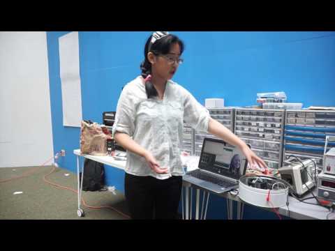
For my final video, I centrifuged jam. Jam is a heterogeneous mixture, which means that it is composed of different substances that aren’t evenly spread out. Because the substances aren’t of equal densities they will naturally separate after a while due to gravity.The centrifuge separates substances at up to 10,000 times the force of gravity, reducing the separation time. After 30 minutes of centrifuging at around 6 volts, we checked the jam and saw that it had separated.
For my first modification, I added a tachometer, which calculates how fast the motor is spinning (in RPM) and prints it out on a LCD. In the centrifuge there is an LED and an infrared phototransistor placed under and over the rotor head respectively. The phototransistor gets a signal from the LED. There are protrusions on the rotor head that, when the rotor head spins, block the signal from the phototransistor to the LED. By measuring how long the signal is blocked during each rotation, the tachometer can calculate the RPM. My modification also has a potentiometer, which is a variable resistor, so that you can manipulate the speed of the motor after getting a reading from the tachometer. This is important because different substances have different densities, so it makes sense to have a different rotor speed for specificity.
While making this modification I struggled with many wiring and coding issues, especially between the IR phototransistor and the LED. Also, the LCD I was using had a shield on it that had different output pins than the LCD itself, making the code essentially useless. To fix these problems, we used the serial monitor for Arduino to check the values of the phototransistor and decided to use a photoresistor instead, to better sense the non-infrared red light from the LED. We also ordered a new LCD that doesn’t have a shield on it.
Tachometer Code:
volatile byte rpmcount;
unsigned int rpm;
unsigned long timeold;// include the library code:
#include // initialize the library with the numbers of the interface pins
LiquidCrystal lcd(7, 8, 9, 10, 11, 12);void rpm_fun()
{
//Each rotation, this interrupt function is run twice, so take that into consideration for
//calculating RPM
//Update count
rpmcount++;
}void setup()
{
lcd.begin(16, 2); // intialise the LCD//Interrupt 0 is digital pin 2, so that is where the IR detector is connected
//Triggers on FALLING (change from HIGH to LOW)
attachInterrupt(0, rpm_fun, FALLING);//Turn on IR LED
pinMode(ledPin, OUTPUT);
digitalWrite(ledPin, HIGH);rpmcount = 0;
rpm = 0;
timeold = 0;
}void loop()
{
//Update RPM every second
delay(1000);
//Don’t process interrupts during calculations
detachInterrupt(0);
//Note that this would be 60*1000/(millis() – timeold)*rpmcount if the interrupt
//happened once per revolution instead of twice. Other multiples could be used
//for multi-bladed propellers or fans
rpm = 30*1000/(millis() – timeold)*rpmcount;
timeold = millis();
rpmcount = 0;//Print out result to lcd
lcd.clear();
lcd.print(“RPM=”);
lcd.print(rpm);//Restart the interrupt processing
attachInterrupt(0, rpm_fun, FALLING);
}
Electrical Schematic of Tachometer:

Diagram courtesy of: http://arduinoprojects101.com/arduino-rpm-counter-tachometer/
Milestone 2: Testing the Centrifuge
I’ve decided to use body wash to test my centrifuge. The body wash I’m using has a high water content, which I’m going to be separating from the rest of the gel. The microcentrifuge separates liquids out of solutions based upon density, so the less dense water will be separated from the more dense gel.
After wiring all my electrical components I 3-D printed important elements of my project: the rotor head, which holds the pipettes as they spin, and motor clamps to keep the motor upright. I decided to change an element of my project: instead of having arms that hold bullet shells and spin outward, I have a more compact rotor head that is attached to the motor shaft.
I 3-D modeled my own rotor head, based on a model I found here, on SolidWorks, which is a computer-aided design (CAD) program.
I’ve also decided to affix my Arduino and motor driver to blocks of wood and attach the wood to my tin instead of just attaching them to the tin. This ensures that the metal on the bottom of the components doesn’t touch the metal to the tin. I had already drilled holes into my tin, but did it on the bottom so that it would be easier. What I didn’t take into account, however, was that the holes of my Arduino aren’t symmetrical, so when I tried to put it in, it didn’t match up with my holes in the tin.
I dealt with many problems while completing assembly, specifically involving computer-aided designing and 3-D printing. At first, the rotor head I printed was too hollow and broke during testing. We modified it to be shorter to easily fit into my tin before 3-D printing it again with less hollowness. Also, when I first designed my motor clamps, I made them exactly the diameter of the motor without taking shrinkage into consideration, so I had to modify the design to be bigger.
Milestone 1: Electrical Components and Programming
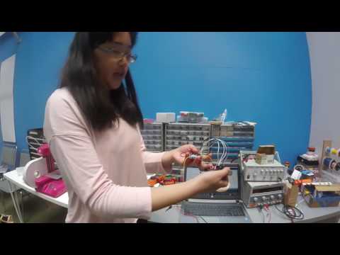
For my first milestone, I wired my Arduino Uno to my motor controller (I’m using the L298N Dual H-Bridge Motor Controller) and motor, and programmed my Arduino. I got my code from this Instructable, and modified it to fit my project.
The motor is controlled by a keyboard; when the keys 1, 2, or 3 are pressed, the motor will go forwards, stop, and go backwards, respectively. I communicate with the motor through my Arduino Uno, a programmable microcontroller, which is connected to the motor driver, a current amplifier.
At first, I encountered many problems with the programming, as it is designed for 2 motors and I only have 1. I had deleted the lines for motor 2, but missed some, so the Arduino was confused about the seemingly unrelated lines of code. I fixed this, and the code successfully uploaded to my Arduino. After doing this, I tested it out to see if the motor would spin. It didn’t, and I thought it might be a connectivity problem. I checked my wiring and redid it, but it still didn’t work. It turned out that one of my jumpers wasn’t in the right place and not enough power was getting to it. We used a DC Power Supply to power it, and after increasing the current, the motor worked.
Code for Centrifuge (Keyboard Control)
//
// 1 -Motor 1 Left
// 2 -Motor 1 Stop
// 3 -Motor 1 Right// Declare L298N Dual H-Bridge Motor Controller directly since there is not a library to load.// Motor 1
int dir1PinA = 2;
int dir2PinA = 3;
int speedPinA = 9; // Needs to be a PWM pin to be able to control motor speedvoid setup() { // Setup runs once per reset
// initialize serial communication @ 9600 baud:
Serial.begin(9600);//Define L298N Dual H-Bridge Motor Controller PinspinMode(dir1PinA,OUTPUT);
pinMode(dir2PinA,OUTPUT);
pinMode(speedPinA,OUTPUT);}void loop() {// Initialize the Serial interface:if (Serial.available() > 0) {
int inByte = Serial.read();
int speed; // Local variableswitch (inByte) {//______________Motor 1______________case ‘1’: // Motor 1 Forward
analogWrite(speedPinA, 255);//Sets speed variable via PWM
digitalWrite(dir1PinA, LOW);
digitalWrite(dir2PinA, HIGH);
Serial.println(“Motor 1 Forward”); // Prints out “Motor 1 Forward” on the serial monitor
Serial.println(” “); // Creates a blank line printed on the serial monitor
break;case ‘2’: // Motor 1 Stop (Freespin)
analogWrite(speedPinA, 0);
digitalWrite(dir1PinA, LOW);
digitalWrite(dir2PinA, HIGH);
Serial.println(“Motor 1 Stop”);
Serial.println(” “);
break;case ‘3’: // Motor 1 Reverse
analogWrite(speedPinA, 255);
digitalWrite(dir1PinA, HIGH);
digitalWrite(dir2PinA, LOW);
Serial.println(“Motor 1 Reverse”);
Serial.println(” “);
break;case ‘5’: // Motor 1 Stop (Freespin)default:
// turn all the connections off if an unmapped key is pressed:
for (int thisPin = 2; thisPin < 11; thisPin++) {
digitalWrite(thisPin, LOW);
}
}
}
}
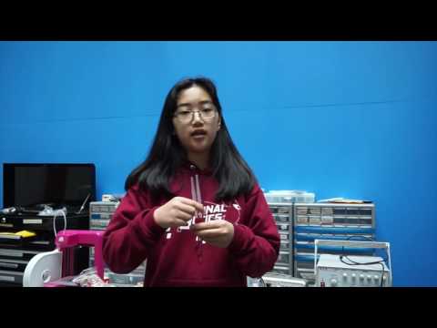
Starter Project: Gram Piano

The Gram Piano is a pre-programmed, mini electronic keyboard that has capacitive touch keys.
The Gram Piano is powered using 2 AA batteries affixed to the printed circuit board (PCB). When you touch a key, a tiny electrical charge is transferred to complete the circuit, creating a voltage drop at that point. The piano uses capacitors, which are electrical circuits that store and release energy by an alternate current (AC). They are composed of 2 conductive electrodes separated by an insulating gap. When your finger comes to rest, a capacitive current is formed and the AC generated within the device induces a corresponding current within your body, which helps span the gap and complete the circuit. The electric current is sent to the microcontroller, which outputs the signal to the speaker and produces the tone.
Extra components of the piano are the potentiometer, which allows you to choose among 3 different octaves, and a button that, when pressed, automatically plays a pre-programmed tune. There are 2 LED’s, one that lights up when on and one that shows the status of the keyboard.
During testing, I realized that the sound was lagging and the keyboard only worked sporadically. After examining the back of the printed circuit board (PCB), I saw that one of my solder joints for the speaker wasn’t very good, so I redid it.
What I Learned:
By making the Gram Piano, I learned:
- How to solder
- The importance of polarity
- How resistors, capacitors, and the rest of the components work
- How capacitive touch works