Kareemot S.

Hi, my name is Kareemot and I am a rising Senior at Bronx Leadership Academy II High School. My starter project is The Minty Boost and my main project is a Voice Controlled Robot. I chose this as my main project because it was a great way for me to learn more about robotics and electrical engineering. These are fields I’ve been interested in since middle school; which is where I participated in my first Lego Robotics class.

Reflection

From the first day to the last, my time here at BlueStamp has been a blast. I came into this program only knowing two things: that I’m interested in becoming an engineer and that I knew nothing about engineering. Now, six weeks later, I have acquired more knowledge on engineering than I expected to. Every day of this program, I have been met with challenges I had to overcome. From these challenges I learned how to problem solve effectively and the importance of being a self learner. The instructors encouraged us students to try and solve problems we were having on our own before asking them, and in doing this I found that I didn’t need their help most of the time.

Coming into this program I expected there to be more boys than girls, and I was right. However, I was wrong thinking that this would negatively affect my experience at BlueStamp. Everyone here is extremely nice and supportive of each other. Most of all, they’re extremely passionate about their project and this made me enjoy being here even more.

I do plan on studying engineering when I go to college next year. I still don’t know which field I want to get into, but I can’t wait to see where I will end up in the future.

Engineer

Kareemot S.

Area of Interest

Robotics and Electrical Engineering

School

Bronx Leadership Academy II

Grade

Incoming Senior

Final Project
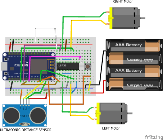
For my final milestone I successfully fixed the issues I was having with my robot and added modifications. One issue I was having with my robot was getting the voice control to work. When I reviewed my code for the voice control, I realized that there was a typo in my code. Once I corrected the typo the voice control began to work just fine. I was also having issues with the app I created to control the robot. When I would press a button on the app, it wouldn’t match with the action of the robot. For example, when I would press the forward button on the app it would move right. It turns out that the reason it was doing this was because when I was wiring my breadboard I had put the positive wire in the negative line and the negative wire in the positive line. As a result, all the charges of my wires were flipped and did not match the code I found online. Instead of fixing the wiring, I decided to edit my code to match the movement of my robot. Once I did this everything worked properly. Lastly, I chose to modify my voice controlled robot by adding an ultrasonic sensor to the front. This sensor stops the robot from moving whenever it comes within eleven centimeters of an object.
wiring-for-voice-control-robot-with-sensor_bb

Third Milestone

For my third milestone I was finally able to use the app I created to control my robot. To do this I had to have my robot and app working on the same WiFi network. This was a difficult process since my robot and app weren’t connecting to my phone’s WiFi Hotspot. However, after many tries, they finally did. After this, I had to upload code to my NodeMCU that would allow it to understand commands sent to it from the app. Once I uploaded the code I was confused as to why my robot was not working, but after going through my code I realized that I never typed in the WiFi password. As soon as I did this, my robot was able to go ‘Forward’, ‘Backwards’, ‘Right’, ‘Left’, and ‘Stop’ using the buttons on my app.  

Second Milestone

robot-app-screenshot
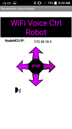
For my second milestone I developed an app through MIT App Inventor. I will use this app to control my voice controlled robot. When a button is pressed or a voice command is given in the app, a request is sent to the IP Address of my robot’s NodeMCU using ‘http’. Only when this request is sent will the robot move. I faced many difficulties while building this app since it was my first time using MIT App Inventor. Many of the functions on it were very confusing so I ended up spending a lot of my time watching and reading tutorials on how to use them. However, finding a way to download the app onto my phone without having to upload it to the App Store was the hardest part of this whole process. I used various methods to try and download it onto my phone, and the way that finally worked was fairly simple. All I had to do was drag my app’s file onto my phone’s memory and then download it onto my phone from there.

First Milestone

My first milestone was getting the motors of my robot to work. This involved assembling the chassis of the robot. Screwing on both motors, a swivel wheel, and a battery pack onto the acrylic plate took longer than I expected since the screw holes were off by a little due to the acrylic plate being laser cut.  Once these parts were on I finally stuck the breadboard–which was already connected to the NodeMCU and the H-Bridge–onto the chassis. The NodeMCU and H-Bridge are extremely important to this project because the NodeMCU is needed to give the robot commands and the robot could not move around without the H-Bridge–which provides voltage to the motors allowing them to operate. To test if my motors worked, I had to upload code I found online to the NodeMCU.  This was a difficult process because I never coded before. However, with the help of Google and my instructors I was able to further my knowledge of coding.

Starter Project

For my starter project I chose The Minty Boost. The Minty Boost is a small battery powered portable USB charger capable of charging virtually any device with a USB cable.                                                                                                                                         To start assembling my Minty Boost, I had to solder on many different parts onto a circuit board. These parts included: five resistors, two ceramic capacitors, a schottky diode, an IC socket, a power inductor, two electrolytic capacitors, and a boost converter chip. In doing this, I accidentally soldered on two of the resistors–which control the flow of the electrons–into the wrong places. To correct this error I had to desolder them using a desoldering pump. This process was very difficult and time consuming, but with great persistence I was able to get the two resistors out and place them in the correct place. Once all the pieces were soldered onto the circuit board I had to connect the circuit board to the battery. Unfortunately the two wires that were supposed to connect the two kept snapping. To fix this issue I soldered the wires onto stronger wires that wouldn’t snap as easily. To finish it off I wrapped the wires in electric tape to prevent them from interfering with other parts of the circuit board. At this point all I had left to do was to connect the USB connector and test the Minty Boost. Since my Minty Boost was successful in charging my phone, I was finally able to place it into the Altoids box.                                                                                                                                   Instructions On How To Build The Minty Boost Can Be Found Here

Leave a Comment

Start typing and press Enter to search

Bluestamp Engineering