Third Eye for the Blind
The Third Eye for the Blind uses an ultrasonic sensor to measure different distances. It also has a vibrating motor that will vibrate, an LED that will light up, and a Piezo buzzer that will buzz when an obstacle approaches. This project is designed to help blind people locate where they are walking.
Engineer
Kaaya M.
Area of Interest
Biomedical Engineering
School
Saratoga High School
Grade
Incoming Sophomore
Reflection
Overall, attending BlueStamp was a great experience for me because I learned so many things that I can use later on in my life, for example in robotics. Also, I learned how to use ultrasonic sensors and how to code on Arduino. I’ve also I learned several life skills like to be patient and never give up. There were some times in the process of making this project that I was really unhappy with the little progress I was making, but I didn’t let that get in the way of the future progress I made. I’m also happy that I attended BlueStamp because I have met several people who have become my friends over the last four weeks.
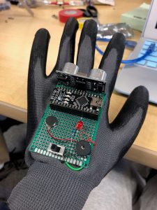
Final Milestone
This is a picture of my finished project. The ultrasonic sensor will sense different distances and in response, the vibrating motor will let the user know that an obstacle is near. Also, an LED will light up to notify the user as well.
Second Milestone
This is a picture of the back of the printed circuit board. These are all the wires I soldered that connect all the components together.
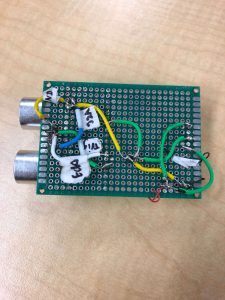
For my second milestone, I finished soldering all the wires that connect all the components on the printed circuit board together. First, I had to solder wires from each of the four pins on the ultrasonic sensor. I soldered the GND pin to the GND pin on the Arduino, the VCC pin to the VIN pin on the Arduino, the Trig pin to pin 12 on the Arduino, and the Echo pin to pin 10 on the Arduino. I also soldered a wire from the negative end of the buzzer to the negative end of the LED, and then another wire from the negative end of the LED to the GND pin on the Arduino. Then I soldered another wire from the positive end of the buzzer to the first leg of the switch, and then another wire from the positive end of the buzzer to the third leg of the switch. Lastly, I soldered a wire from the middle leg of the buzzer to the positive end of the LED, and then another wire from the positive end of the LED to pin 5 on the Arduino. An obstacle I ran into while completing this milestone was that often times I had to solder multiple wires at one joint, and I put too much solder, which meant that I had to desolder and then a wire would come out. It took lots of time to solder the wires again, but it was a good experience for me to learn.
In the future, I plan to glue the PCB to the glove to make my project more portable. Also, I plan on finishing my code for the Arduino and doing some test runs for my project.
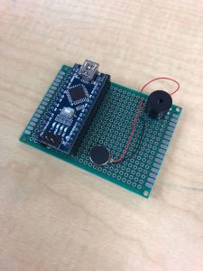
First Milestone
This is a picture of my printed circuit board. It has two female header pins and a buzzer soldered to it. I also soldered the red wire from the vibrating motor to the positive end of the buzzer, and the black wire to the negative end of the buzzer.
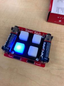
Starter Project
This is a picture of my finished starter project, the Simon Says Game.