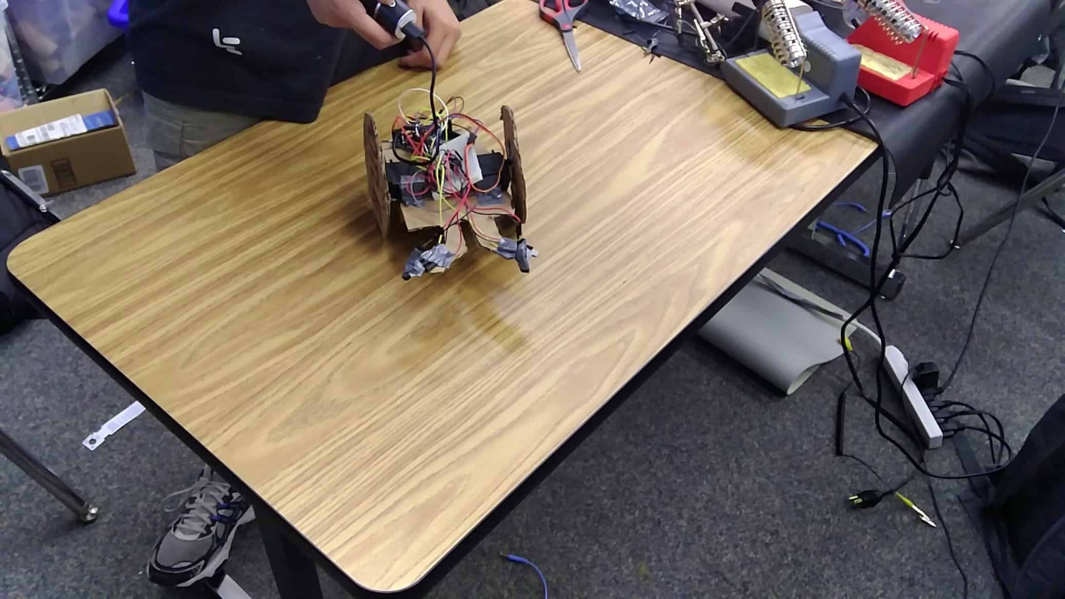
Tabletop Wandering Robot

Engineer

Justin L.

Area of Interest

Computer Science

School

Cupertino High School

Grade

Rising Sophomore

Tabletop Wandering Robot is a robot that has the ability to move around on a tabletop without falling off the edge. It uses phototransistors and LED lights to detect the edges of a table. The robot will detect edges by sending infrared light downward and detecting if it’s being reflected back.

Third Milestone

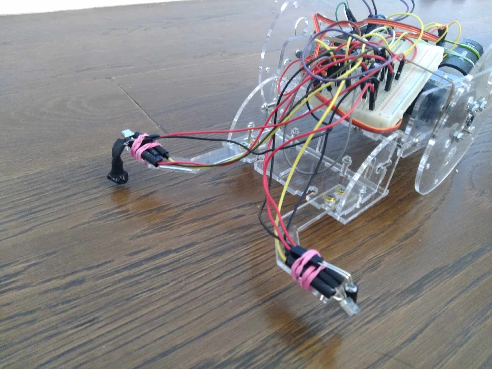
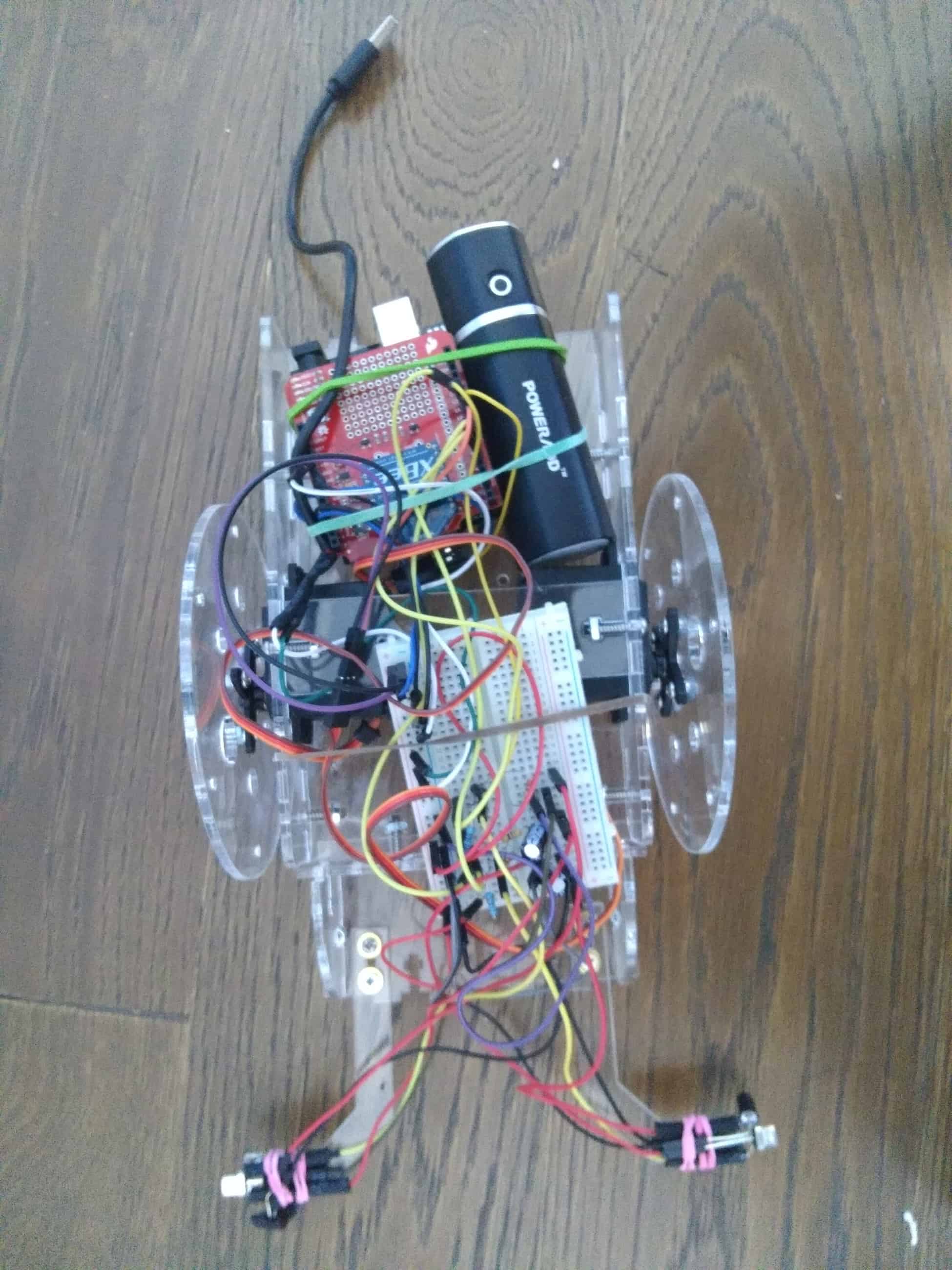
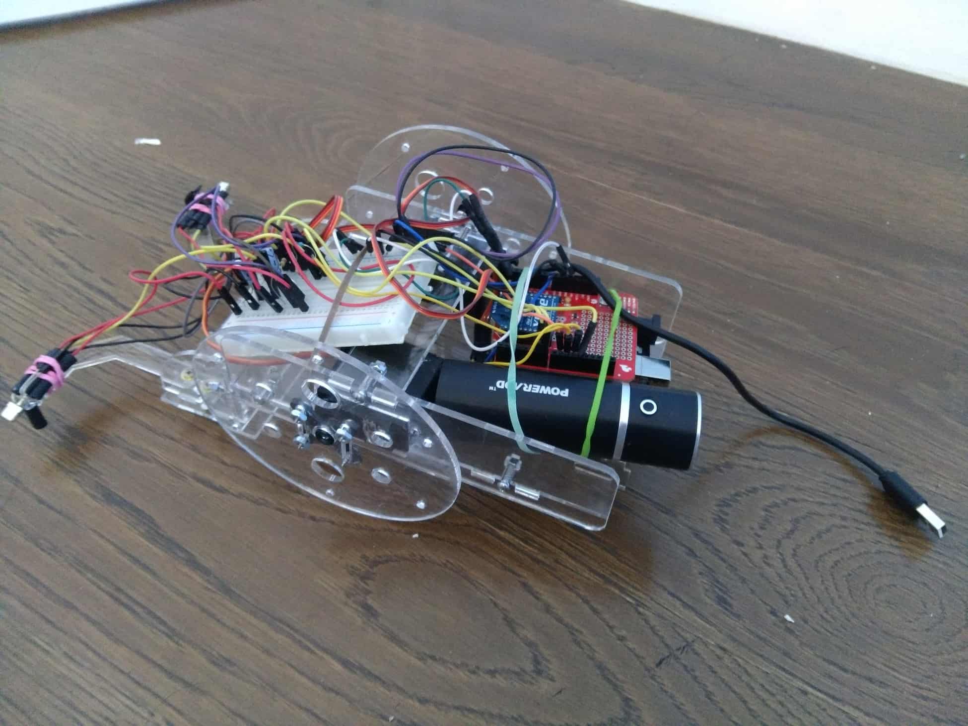
The third milestone includes me assembling the acrylic chassis. A major issue I faced was assembling the the wheels. As you can see in the image slide show above, in the final version of the chassis, there are screws sticking out the wheel. At first, I assembled the wheel by screwing in the screws in the other direction, however, that results in the screw getting stuck on the chassis or servo because they are too long. Also, there are no place for putting screws on the servo horn, so to do that, I forced in some mechanical screws on some tiny hole on the horn.
If you look closely at my robot, you can see a XBee shield (that doesn’t serve any function yet) on it. This was because I actually had a modification that I made before the chassis arrive. However, the modification stopped working and I didn’t have the time to fix it. I will make an update if I fixed the issue.

Second Milestone

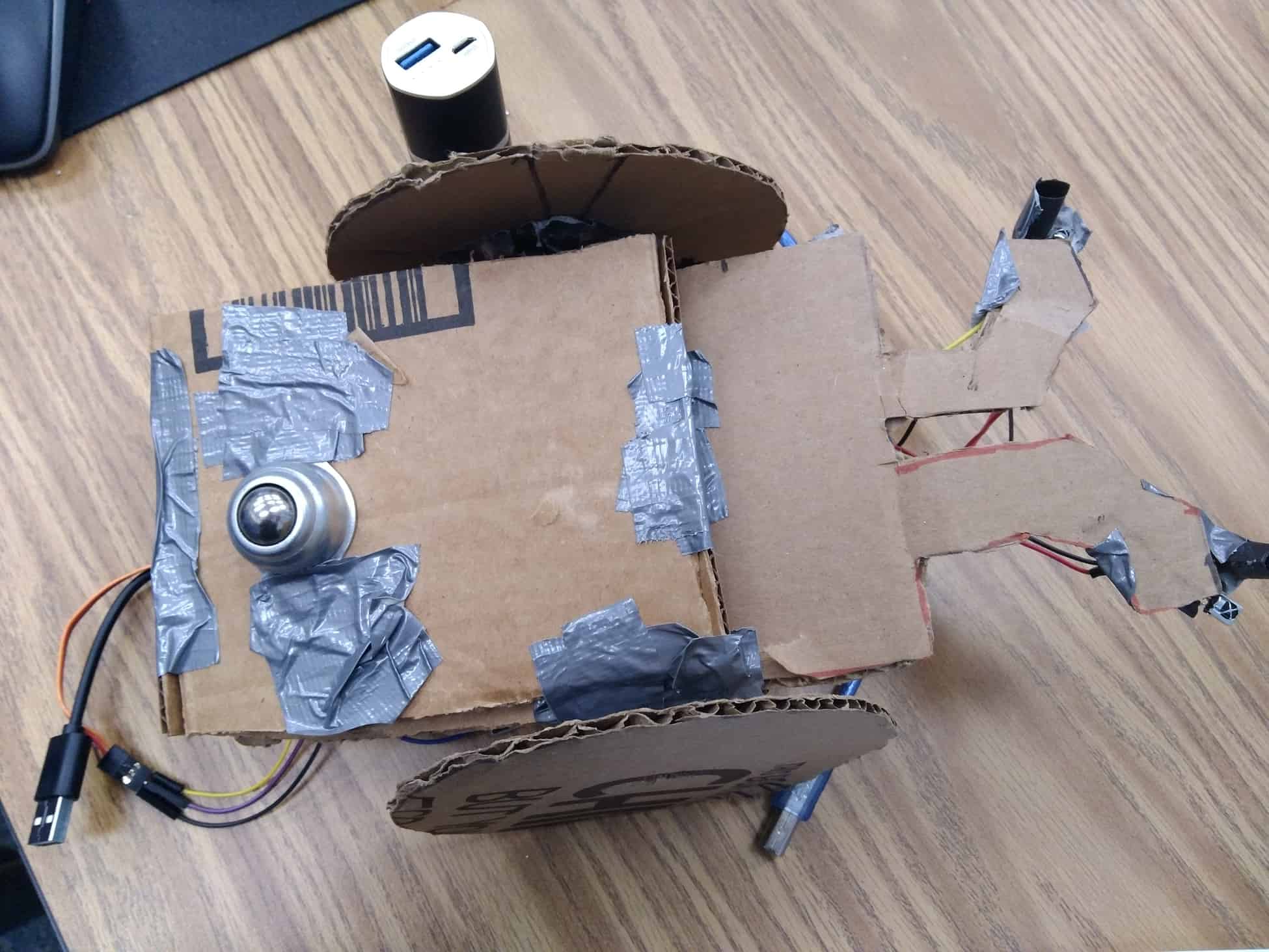
The second milestone includes improving on the circuit, making the prototype chassis, and mounting my circuit on the prototype.
In truth, I didn’t plan on improving much on the circuit much before and right after the first Milestone. I planned to use the schematic I created in my previous Milestone and connect a new pair of IR sensors and servo on. however, I ran into some issues. I realized that my sensors are not sensitive enough. I tried to increase the current on my emitter to make it emit more IR, although it did increase the range, it’s still not enough for the sensors to pick the signals which are reflected back from the table. I gave up on using the insensitive detectors and instead used some three pin detector, which have a digital output. The problem with three pin detectors is that they are designed for receiving short length signals which sends complicated messages. This is why I only check the detectors every 40 mS and only turn on the emitters when I’m checking the detector. I also had to use Tone() to set a frequency of my emitter flashing when I turn it on.
Assembling and mounting the prototype chassis is actually fairly easy compared to the process I went through improving my circuit. I chose to use duct tape and cardboard as my materials for the prototype. After connecting the wheels to servo and the servo to the chassis’ bottom piece, I had to use a box as a set to keep the wheels off the ground for testing. That is how I decided where to place my detectors & emitters. Next, I had to stick the small caster on the bottom of chassis, so I lowered the height between the bottom piece and the table by sticking on a small box I made.
final-sketch

First Milestone

My intensive project is Tabletop Robot. For this milestone, I worked out most of the circuit for my project. I connected one pair of IR detector, IR emitter, and servo to my project. For my detector, the power is connected to both an analog pin on my servo, and the ground. However, a diode is between the ground and the power, and that is my IR detector. If the detector is not receiving any IR light, it won’t allow any electrons to pass through, therefore the analog pin will receive five voltage. If the detector allows electrons to pass through, the analog will receive lower than five voltage because some of them go to ground.
There are several problems that I ran into. The first one was not receiving any signal between my IR emitter and detector. This turns out to be an error in my circuit, I realized my emitter is not emitting any infrared when I tried to see it with my phone camera. I found out the resistor I used to have way too much resistance, so it worked after I changed my resistor. The second problem is to power the entire circuit. If I plug my power into my Arduino and let the Arduino to power the rest of the circuit, then my servos won’t get supplied with enough current. To solve this, I powered the breadboard directly with my power bank and powered the Arduino from my breadboard to 5v pin (which I originally thought is an output only pin).

Starter Project

My starter project is Mintyboost. It is a charger for mobile devices which uses two AA batteries as power source. It contains a circuit board, a battery holder with two AA batteries, a boost converter chip, a power inductor, an IC socket, 5 resistors, 4 capacitors, a diode, and a female USB jack. All of these components have to work together for Mintyboost to work. The batteries provide the energy to charge the phone, they are connected to the board through the holder. The batteries have a three voltage output, however, the USB port uses a five voltage output. In order to charge through the USB port, a conversion of voltage needs to take place. There are two components involved, boost converter chip and power inductor. Power inductor is a coil of wires, whenever electrons pass through, a magnetic field would be created and stores all the energy inside. The boost converter has two modes: current mode and burst mode. It switches the mode, and with the inductor, they store the power passing through, convert it to five voltage, then generate it out.
The process of making the project benefited me a lot more than the deliverable I made itself. First of all, I learned soldering is not an easy process, and it takes practice to master. During the process of making Mintyboost, not only did I have to solder all the parts onto the circuit board, I also had to desolder the diode and solder it back on since I soldered it on the wrong direction. The wires from the battery holder also fell off plenty of times. Desoldering and soldering the wires back on are great opportunities for practicing them. At the end, the conductor ring in the hole for putting in the positive charge wire from the battery holder fell off because I applied it with heat too many times. To solve this problem, I learned to use a multimeter to check current flows in my circuit. I checked the circuit schematic, then I realized the original hole leads to C1 resistor. I short circuited the original positive charge wire to one of C1 resistor’s lead, and the Mintyboost works fine.

Leave a Comment

Start typing and press Enter to search

Bluestamp Engineering