
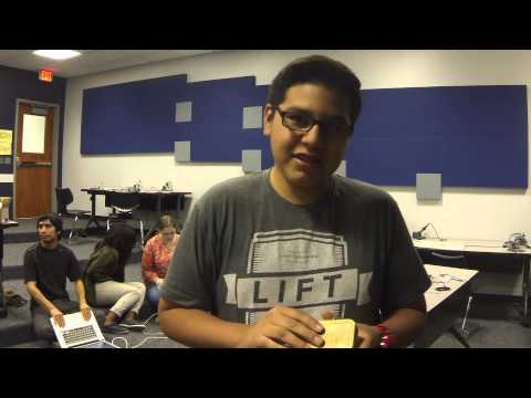
Hello, my name is Joshua and I go to KIPP generations, where I’m a rising freshmen. For my starter project, I am building a Minty Boost witch is really a portable charger; for my main project; I am building an R/C tank with a PSP controller by programming it to the Arduino to tell it what to do.

My building materials are the Arduino, motor shield, treads, wheels, battery pack, gear box, screws, wires, camera, sd card holder, micro sd card, and sd card adapter.
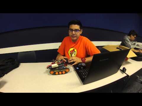
This is my final blog post, so this is going to be a summary of my project. My project is a R/C tank that is controlled with a PSP controller, and in order to use that you need a wireless receiver that is connected to the PSP controller and the Arduino so they can communicate to tell the motors what to do. My camera is simple, really: the program tells the camera that if motion is shown on the camera, then take the picture and when that is finished, it is stored onto the micro sd card.
For my second milestone, I had changed the structure of my tank by instead of taping the gear box to the board, I super glued it to the board and used double sided tape to tape the Arduino to the the tank. I placed the battery pack on top of everything and used zip ties to tie it to everything--it looks better and is sturdier than the last model. I had also added a camera onto it with a sd card to store the pictures, and I used a breadboard for that because it had a sticky part at the bottom of the breadboard and I used that to attach it to the battery. https://learn.adafruit.com/ttl-serial-camera/
This is my first milestone and I was able to drive the tank around and was also able to control it with the PSP controller. The most challenging thing to do to make the tank was the gearbox because I would have all the gears in place and it would fall out, so my advice is to have someone else be there to hold all the gears so they won’t fall out. Then, my gearbox would not fit on the board so I had to tape it to the board and tape everything else to everything. http://www.billporter.info/2010/06/05/playstation-2-controller-arduino-library-v1-0/

This is schematic of the wiring of the wireless receiver to the Arduino; this is also the programming of the tank.
#include <PS2X_lib.h>
PS2X ps2x;
int right_motor_direction = 12;
int right_motor_speed= 3;
int left_motor_direction = 13;
int left_motor_speed = 11;
void setup() {
pinMode(right_motor_direction, OUTPUT);
pinMode(left_motor_direction, OUTPUT);
Serial.begin(9600);
ps2x.config_gamepad(7,5,10,6, false, false);
}
void loop() {
ps2x.read_gamepad(false, 0); //read controller and set large motor to spin at ‘vibrate’ speed
Serial.print(“Left: “); Serial.println(ps2x.Analog(PSS_LY));
Serial.print(“Right: “); Serial.println(ps2x.Analog(PSS_RY));
if(ps2x.Analog(PSS_RY) < 127) {
digitalWrite(right_motor_direction,HIGH);
analogWrite(right_motor_speed, map(ps2x.Analog(PSS_RY), 128, 0, 0, 255));
}
else if(ps2x.Analog(PSS_RY) > 127) {
digitalWrite(right_motor_direction,LOW);
analogWrite(right_motor_speed, map(ps2x.Analog(PSS_RY), 128, 255, 0, 255));
}
else {
analogWrite(right_motor_speed, 0);
}
if(ps2x.Analog(PSS_LY) < 127) {
digitalWrite(left_motor_direction,HIGH);
analogWrite(left_motor_speed, map(ps2x.Analog(PSS_LY), 128, 0, 0, 255));
}
else if(ps2x.Analog(PSS_LY) > 127) {
digitalWrite(left_motor_direction,LOW);
analogWrite(left_motor_speed, map(ps2x.Analog(PSS_LY), 128, 255, 0, 255));
}
else{
analogWrite(left_motor_speed, 0);
}
delay(50);
}
http://paulbleisch.com/blog/2013/01/03/simple-remote-controlled-arduino-tank/

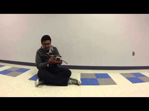
This is my starter project witch is the Minty Boost or a portable charger. I had to solder a lot of components onto a small board so I had some issues with soldering, when I soldered the components on backwards and it took a long time to get them out and out them back in.
at 13:24Sorry, I don’t have any manufacturing caipcaty, and handling the ordering of parts, soldering, payment, shipping to interested parties, and possible support and returns issues is something that I’d rather not do, but rather focus on learning new stuff and writing about that in here (if I’d price my time, the password generators would also become prohibitively expensive, something like 40e282ac a piece). Of course, if you like the blog, you’re also welcome to donate via PayPal (donations over $10 get a free ATtiny2313 header PCB while they last :).I recommend you to check out YubiKey, which is a commercial solution that’s in many ways superior (consumer-grade, more versatile) to the DIY solution if you’d rather like to buy a ready-made unit. And as said, Ben might still have boards if you have a solder iron and the parts (and ISP programmer) yourself.jimmy says:October 30, 2012 at 20:07all right men i understand, yes ofcourse i like your blog. but i’m just started so i dont know much stuff, that is why i also don’t know what a ATtiny2313 header PCB is. and also no what isp is. but thanks anyway for your reply and your link.but if anyone else like to help me to learn stuff like that i would appreciate it and you’re welcome to replyjokkebk says:October 30, 2012 at 23:33Sure, didn’t mean to be rude either, just thought to explain in detail why not! 🙂 If you are just starting, take a look at my V-USB tutorial, it’s rather beginner-friendly and contains some pointers to get you started. I can also recommend avrfreaks.net forums, they have a nice tutorial section. Welcome to the world of electronics!jimmy says:October 31, 2012 at 20:11I think this is a misunderstand because i didn’t thought that you where rude 😉 so it’s okay. I defenetly wil take a look for that tuto’s. again thanks for the link, and i wish you the best with your blog