Smart Mirror
Hi, my name is Josh, and I am an incoming freshman at Frisch. My main project is the Smart Mirror. My starter project is the TV-B-Gone.
Engineer
Josh K.
Area of Interest
HCI and AI
School
Frisch
Grade
Incoming Freshman
Reflections
I really enjoyed all the independence at Bluestamp. Everyday, I was told that I had 4 and a half hours to go and figure everything out. I learned an immense amount. I also improved my skill at Bluestamp of how to teach myself instead of being taught. I learned a lot of skills I expected to, such as Javascript. I additionally learned some skills I did not expect to, such as how to use all the tools and power tools that were needed to create the frame. After this experience, I will continue to teach myself more information related to coding and mechanical engineering.
Final Milestone
My final milestone was adding extra features to my smart mirror in the form of adding Amazon Alexa. I added the Alexa using Amazon’s Voice Service. Amazon’s Voice Service is an Amazon software available for developers to use to make prototypes of their own Amazon Alexa device. It is not perfect or that easy to use because it is for a developer, but I am using it because it makes the most sense. First, I got the credentials I needed from Amazon in order to obtain access. I signed up for a free Amazon developer account. Then I created a device profile and got a client ID, Client secret after I created a security profile. Then I configured it all on my raspberry pi. This was done by adding credentials to a file called “config.txt”. I then ran the command [Sudo Bash setup.sh Config.txt] in the terminal. Then I authorized it using the instructions given once the [Sudo bash startsample.sh] command is run in the terminal. Then after you authorize it, you run the command [Sudo bash startsample.sh] in the terminal to start the window up. Now it should work. For a more detailed explanation, look at Amazon’s documentation available at: (https://developer.amazon.com/docs/alexa-voice-service/register-a-product.html).
This extra feature took a long time to add, It took me about 1.5 weeks to add, including 1 week of failed attempts and then another 2.5 days of getting the final one to work. This method above was the only method I could find that worked. The biggest challenge was finding a method that worked, and luckily I found one. I am very happy it worked, and I hope to get the autostart, and the sound to work. I also need to do the voice training for the microphone. There is always room for improvements, and I know that it can only be almost perfect, and not perfect.
How Alexa Works
-
Alexa is constantly listening for the word Alexa.
-
When it hears Alexa, it starts listening to what you say after it. It converts what you say into text.
-
It then uses that text to find the answer.
-
It then converts the text for the answer into voice and says it back to you.
As a second extra feature, I configured the Raspberry Pi to have the Alexa autostart on boot. The code for how to do it is added at the bottom of the .Bashrc file in the /home/pi directory. To open this file for editing run the command: (Sudo Nano /home/pi/.bashrc). In this file at the end add what is in the box below.
//Indicates to run the command at boot.

echo Running at boot
// the command to run.

sudo bash /home/pi/startsample.sh
Third Milestone
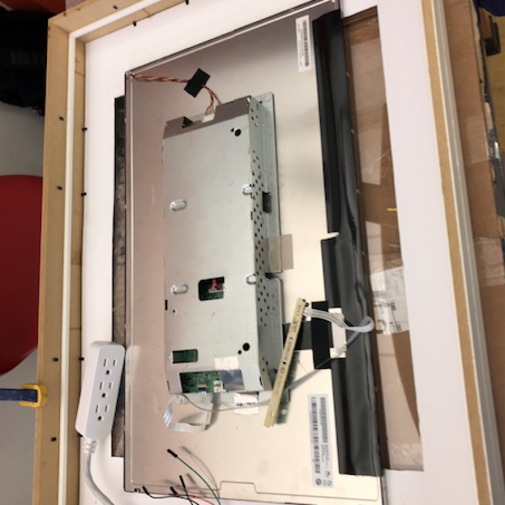
My third milestone was finishing the frame. First, I removed the old broken monitor from the frame and put in the new one. I then installed all the other supporting popsicle stick structures that could not be installed until the new monitor came in. I also added in all the other velcro strips to reinforce the monitor. See Figure 1. I also put the speaker (https://www.adafruit.com/product/1363) and the microphone (https://www.amazon.com/dp/B00IR8R7WQ/ref=cm_sw_su_dp) in the monitor, which was originally going to be part of my second milestone. I disassembled the speaker to put it in, and the microphone has an extension cable which goes to the top, to make sure it hears me right. See Figure 2. I also put the monitor buttons outside the enclosed part of the frame, so it can be pushed to turn the monitor on and off. Then, I cut a hole in the frame to allow the power plugs to be put in without hitting the back of the frame. After that, I wired everything up and tested the mirror. I noticed that when I tested it out, it needed to have an all black background, so the monitor, would not be see through. So I painted some cardboard black and put it in the frame, and then the smart mirror worked great, as seen in Figure 3. The biggest challenge I faced with this milestone was making sure the monitor was in place and secure. I continued to enhance my knowledge of using tools, such as the Dremel and an Exacto knife. In this milestone, I finished my base project. I am excited to do my modifications.
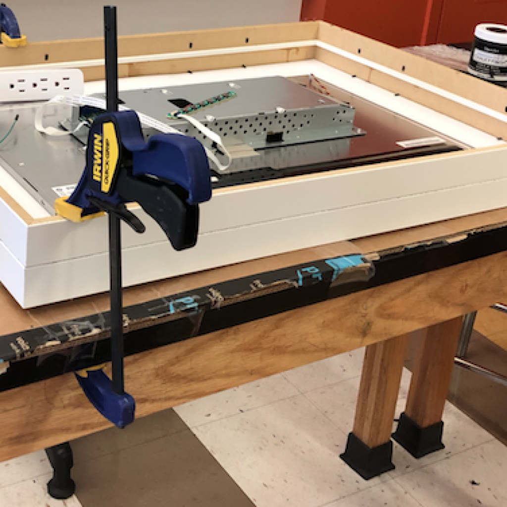
Figure 1
After installing the new monitor, supports and some of the velcro.
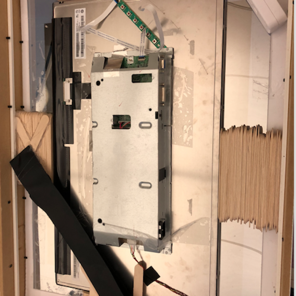
Figure 2
One of the speakers after being installed in the backplate.
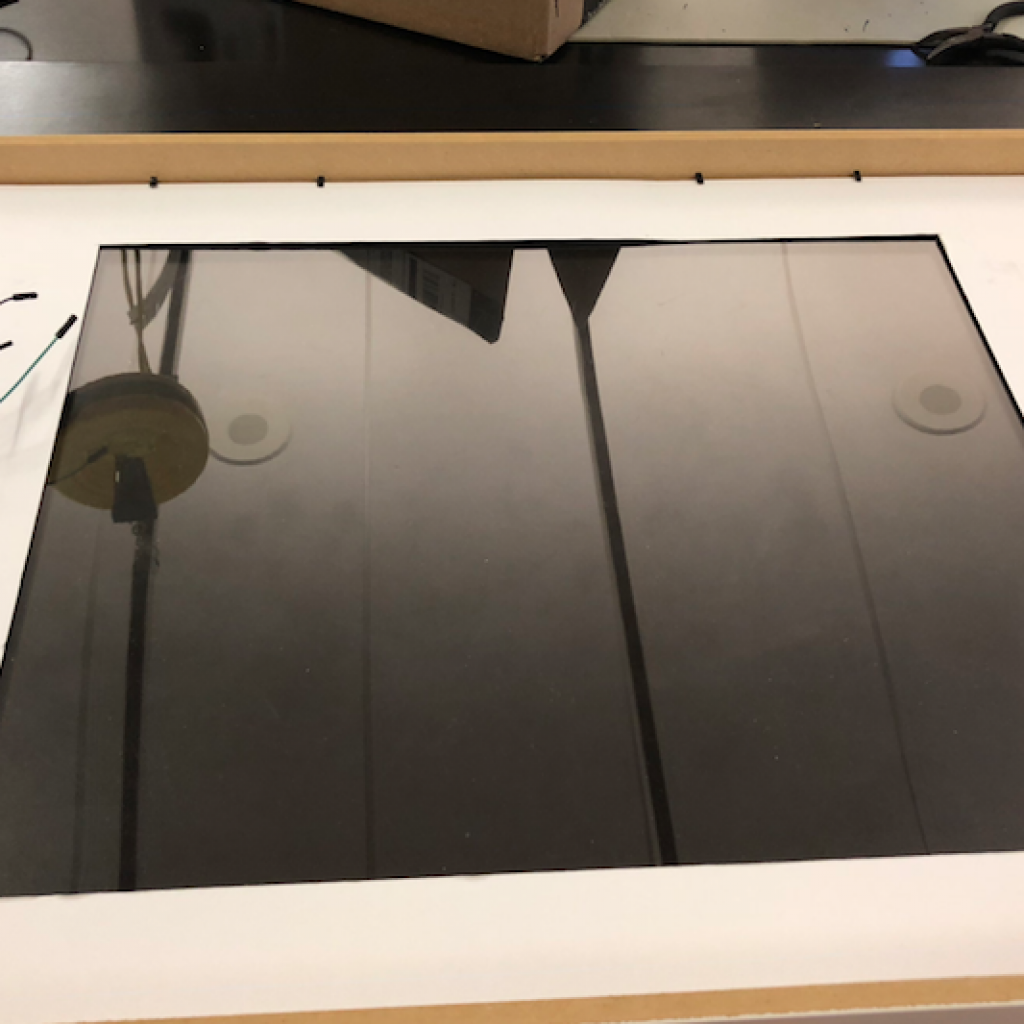
Figure 3
The mirror after being completed.
Second Milestone
My second milestone was starting the frame. First, I disassembled the monitor, which is an HP 24 inch monitor, it can be purchased here: https://www.amazon.com/HP-24uh-24-inch-Backlit-Monitor/dp/B00SFB13UC. I removed the stand, took off the screw and popped it off. I removed the monitor carefully, along with the buttons to control it from the frame. Then, I opened up my frames. I have 2 27 x 19 inch Ikea ribba frame, which can be purchased here: https://www.ikea.com/us/en/catalog/products/30301624/. I also cut holes into them for the power cable and button on the bottom of the side. I will later install and connect up in milestone 3, where I add in all the components and wire up the power cable and button. After that, I epoxied the two frames together. I put the monitor in to test fit it, and then started working on my supporting structures. The supporting structures were popsicle sticks and velcro. I encountered a few problems throughout the course of this milestone. While transporting my monitor to the gluing table, the monitor fell through the frame and broke. I resolved this problem by gluing in the acrylic sheet and reinforcing the supports. However, all my supports cannot be put in until my new monitor comes. But, I need to be ready when it comes to installing it. I learned how to use a lot of tools in this milestone, including a drill, Dremel, saw, exacto knife, and hot air gun.
First Milestone
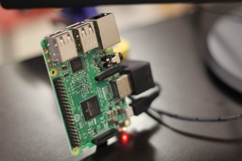
A Raspberry Pi 3, (Image by Josh K. / 2018).
My first milestone was completing the installation of the software for the Smart Mirror. First, I installed NOOBS, the software for the Raspberry Pi 3. The Raspberry Pi is a microcomputer that houses the smart mirror software. It is a very important part of the project. I installed the Smart Mirror Software from GitHub, a website that houses repositories of code and software. I then configured the Smart Mirror Software to start on startup of the Raspberry Pi. After that, I worked on the configuration of the software and adding modules. Modules are pieces of software that add in additional functionality. I used many modules such as the weather forecast, calendars, time of day, and more. There were numerous problems that I faced while installing the software for the Smart Mirror. I corrupted the configuration file and had to go back to a previous version and try again. I also had some issues with getting the API key for the weather software, but eventually, I got one and now it works. Another problem I faced was getting the monthly calendar view above the holiday’s calendar. I could not move it without corrupting the configuration so I left it where it was.
Module Gallery
Weather Modules
I configured the weather module by adding an API Key. An API is a way of communication between the module and the software providing the data, in this case, the weather. The API key is a key that tells the software who I am, what I’m trying to access, and what program is requesting the data.
Tech News Module
I added in a tech news module, that displays tech news. The code is in my custom config file at the bottom of the page.
Regular News Module
I added RSS feeds to the regular news module, to add other sources of news. An RSS feed is a feed from a site that gives specific information and constant updates, so the news instantly comes from the site.
Monthly Calendar View
I added in a monthly calendar view so you can see the calendar for the entire month.
Compliments Module
I changed the compliments module to be specific to me. I made the compliments module say “Good Morning Josh,” instead of just ”Good Morning.”
Custom Code
//You need to space this correctly in order to work.
// WordPress will not allow me to space it.
//This code goes into the config file.
{
module: “newsfeed”,
position: “top_bar”,
config: {
feeds: [
{
title: “Technology News”,
url: “http://feeds.arstechnica.com/arstechnica/technology-lab”
},
{
title: “Technology News”,
url: “http://www.techmeme.com/feed.xml”
},
],
showSourceTitle: true,
showPublishDate: true
}
},
//You need to space this in order for it to work.
//Wordpress does not allow me to space it correctly.
//This code replaces the original config part for the news module.
{
module: “newsfeed”,
position: “bottom_bar”,
config: {
feeds: [
{
title: “New York Times”,
url: “http://www.nytimes.com/services/xml/rss/nyt/HomePage.xml”
},
{ title: “Wall Street Journal World News”,
url: “http://www.wsj.com/xml/rss/3_7085.xml”
},
{ title: “Wall Street Journal Market News”,
url: “http://www.wsj.com/xml/rss/3_7031.xml”
},
{ title: “New York Post”,
url: “https://nypost.com/feed/”
}
],showSourceTitle: true,
showPublishDate: true
}
},
//Replace the original of this in the Compliments.js file.
//You will need to space this correctly in order for it to work.
//Wordpress does not allow me to space it correctly.
defaults: {
compliments: {
morning: [
“Good morning, Josh!”,
“Enjoy your day,Josh!”,
“How was your sleep?”
],
afternoon: [
“Hello, Josh!”,
“You are amazing,Josh!”,
“Looking good today!”
],
evening: [
“Wow, you are really smart!”,
“You are so diligent!!”,
“Hi, Josh!”
]
},
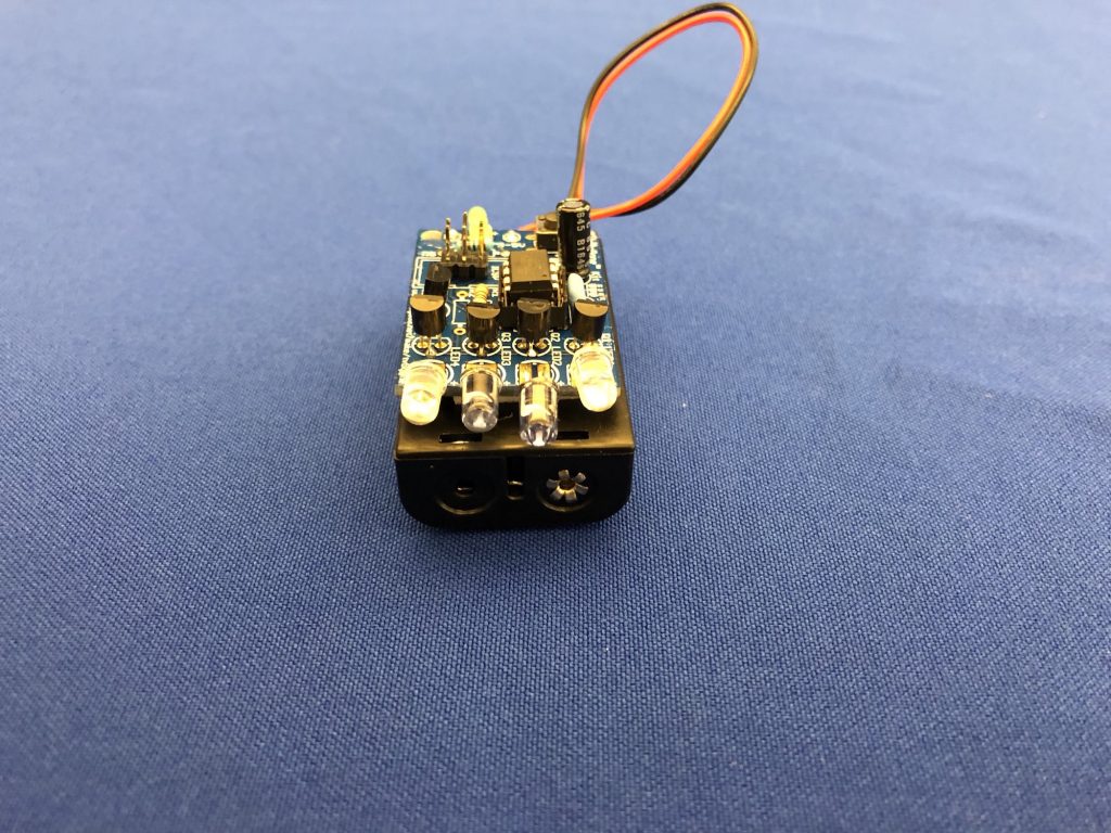
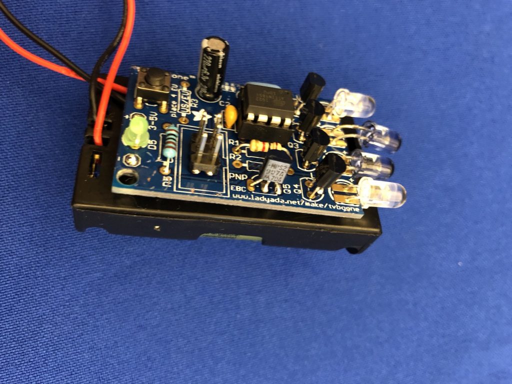
TV-B-Gone
TV-B-Gone Images