
3 Axis CNC Router
A fully functional standalone 3 axis gantry style router. Powered by a Raspberry Pi 3B and a Protoneer GRBL CNC Hat, four stepper motors precisely move a gantry and spindle inside the frame to perform subtractive manufacturing and produce parts with great accuracy.
Engineer
Joe G
Area of Interest
Mechanical Engineering
School
Brooklyn Technical High School
Grade
Incoming Junior
Final Project
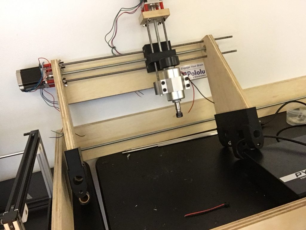
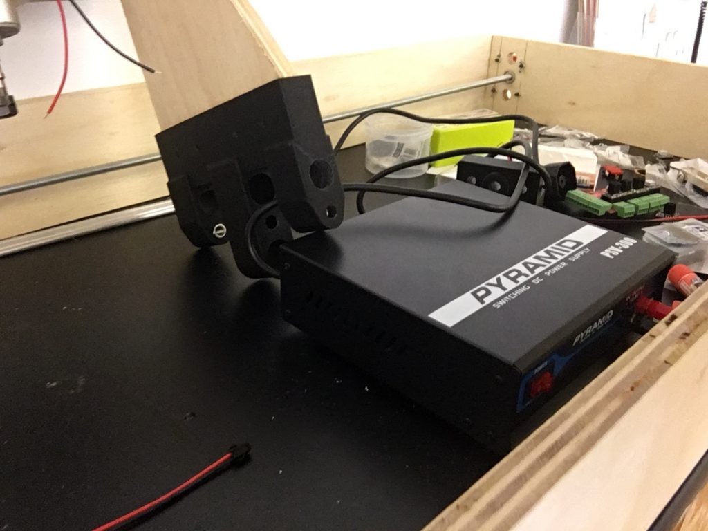
After three weeks and a lot of soldering, I am writing this final milestone while looking at a fully functional 3-axis CNC router. So I want to finally explain exactly what this machine does, how it does it, and how I assembled it from the last milestone.
Having finished most of the assembly of the gantry at the second milestone, I made a few small modifications on the gantry, and then assembled the gantry onto the frame. I ran into an issue with the quality of my materials, as Home Depot’s threaded rods were fairly poor. To deal with this, I used a die to re-cut the threads on them. This worked well with multiple iterations, and the movement of the rods became noticeably smoother. After that, assembly was straightforward. I attached the stepper motors to the threaded rods on the frame, and then wired the steppers to the original Raspberry Pi Hat. This was fortunately the same setup as demonstrated in the first milestone, and made the wiring fairly simple to work with.
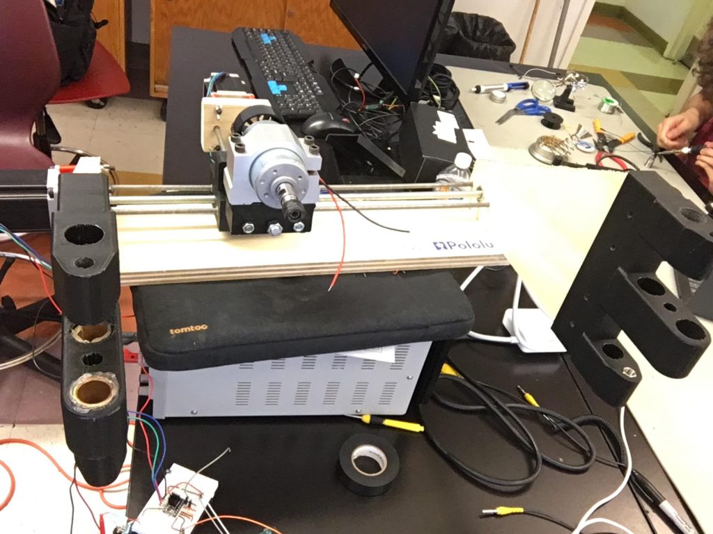
Some pictures of the assembled router below:


Flowchart of the electronics on the router:
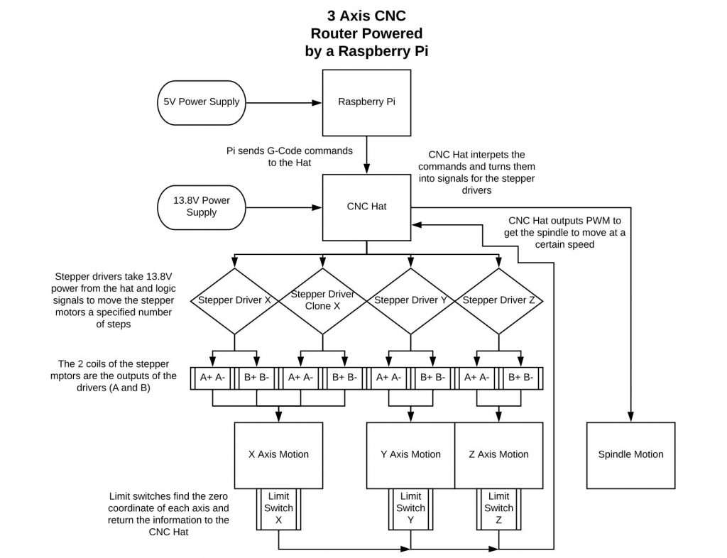
Now we can talk about what a CNC machine is. A CNC machine is essentially moving a point to coordinates in space within its frame. The computer reads lines of code which tell it to move to specific coordinates at certain speeds. This may sound vague when looking at the router I’ve built, and that’s absolutely true, because not all CNC machines are routers. In fact, all 3D printers, laser cutters, PCB engravers, and plasma cutters, all use the CNC process. CNC stands for computer numerical control, and these machines all accomplish different tasks.
This particular machine is a router, meaning it moves a gantry with a spindle around its coordinate space. The spindle is a high power DC motor which spins drill bits, endmills, and other tools, to sculpt away material from a piece of stock. This means that the router starts with some kind of stock piece, and removes material until the final product remains. You might have heard CNC machining as “subtractive manufacturing” and this is where it gets that nickname from. Now granted that I made my router out of plywood and PLA plastic filament, it’s not exactly the most rigid structure at the end of the day. This rigidity issue is a tough problem for all CNC machines, as it means a loss of precision and gives potential for the machine to break more easily. To work to its advantages, my router will likely do its best work in softer materials like plastics, wood, and foam. Metals, although useful, are a notch above what this is capable of, as it’s still just a prototype.
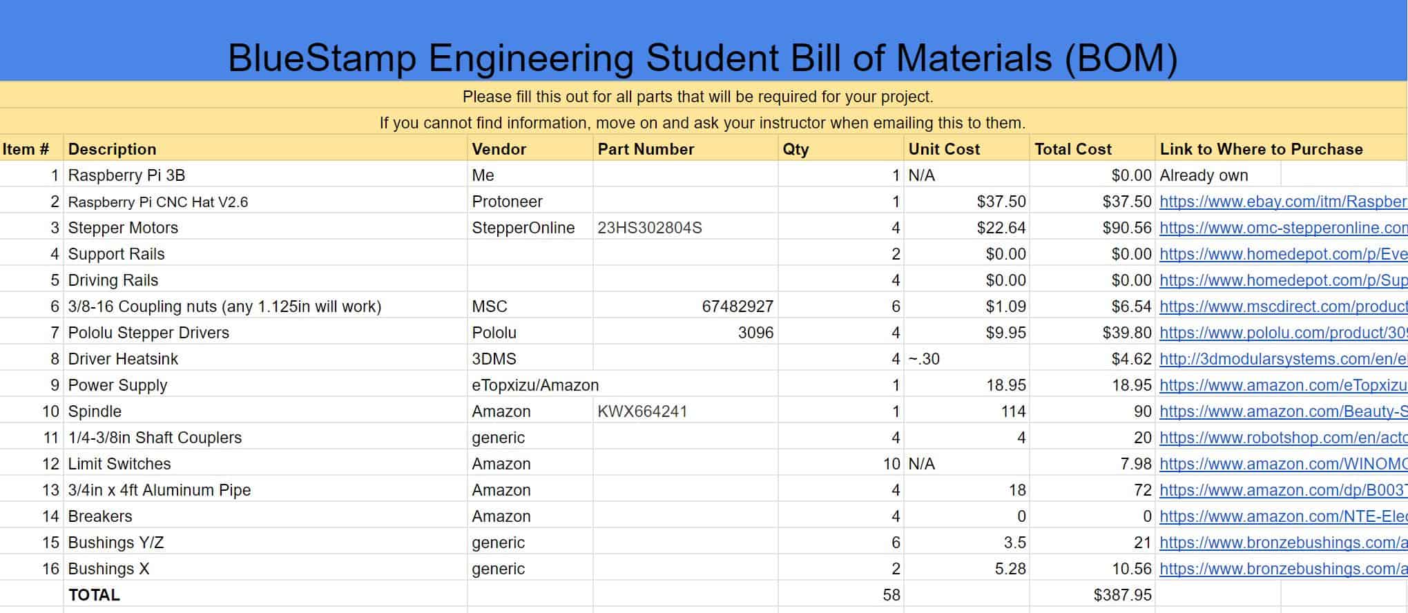
Bill of Materials:


Reflection
Coming into BlueStamp, I was excited at the idea of working on a project of my own design. I was told the CNC router would be a real challenge to design and build in such a short amount of time, and I think I was able to rise to the task at hand. BlueStamp did a great job at helping me manage my time. Working in set time constraints, being asked to document my work, and justifying the purpose of each and every part in my design, did wonders in helping my productivity and clarity throughout the past three weeks. I also refined the design process and got to apply it through multiple iterations of designs. Overall, I enjoyed a positive experience, and hope to continue working on projects such as this going forward.
Second Milestone
The second milestone of fabricating all of the parts and testing movement was done. The highlight of this portion was simply the experience of machining all of the parts needed for such a large project. The two methods of fabrication I used were 3D printing and cutting parts out of plywood. Thankfully, I have the means to make parts outside of BlueStamp, and spent many evenings setting up 3D prints and jigsawing. I printed my parts at home in PLA, a rigid but brittle plastic. This helped tighten tolerances around the design, and ensure the rigidity of the machine as a whole. To 3D print, I also needed to convert my 3D models into code that the printer could understand. This process is called “slicing” a print, and applications are dedicated to the task. I prefered to use Ultimaker Cura when making the parts for the CNC router, but others would have worked fine as well. The prints took quite a while, adding up to more than two full days of nonstop printing. However, the result was absolutely worth it. The parts I ended up with felt excellent, and almost all of the tolerances and dimensions were spot on.
For hand fabricating the wooden parts, I also used a variety of power tools, including a circular saw, hacksaw, jigsaw, and drill press. I made the largest structural parts of the router out of 3/4″ plywood. It too is also a rigid and very strong material at that thickness, certainly a better option than plastic at larger sizes. It comes as no surprise that the wood parts were far more labor intensive to make. I needed precise measurements down to a thousandth of an inch to mark out holes. For this, I used a caliper and a t-square to make my measurements accurate. A caliper is a precise digital measuring tool, and a t-square is a ruler with a perpendicular mount. Both were useful when drawing lines and hole locations.
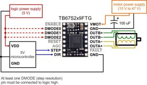
With fabrication almost completely out of the way, I began assembling the router. I assembled the gantry and frame of the router, although I was not able to connect them due to a few missing parts we ordered. The gantry is essentially a bridge-like structure that acts as the support for the horizontal and vertical axes (Y and Z). Finally, I attached the stepper motors and got one axis of the gantry to move with an Arduino microcontroller using the schematic shown below. Although this driver is not mounted on the CNC Hat as in the first milestone, this works exactly the same way.
Some Images From Assembly
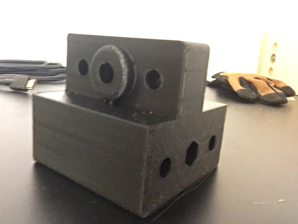
Above, the assembled gantry lying against the frame (1), followed by the power supply (2), the gantry being assembled on another power supply (3), and a 3D printed prototype carriage for the gantry (4).
The router moves at a decent speed, and im pretty pleased with how it’s working at the moment. The next and final step will be assembling everything and hopefully milling some material!
The router moves at a decent speed, and I’m pretty pleased with how it’s working at the moment. The next and final step will be assembling everything and hopefully milling some material!
A side view of the CAD of the gantry above
The pinout of the stepper drivers below
First Milestone
1 2 3 4

5 6 7
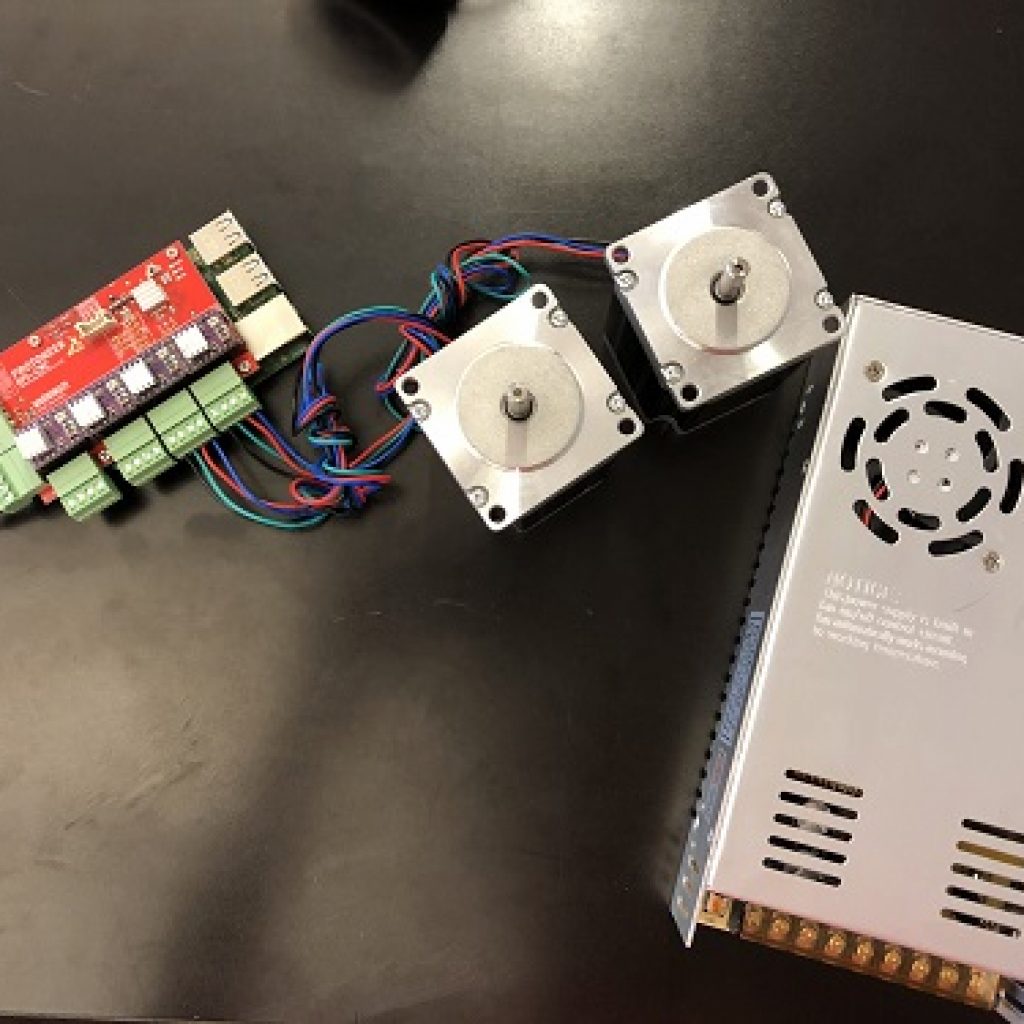
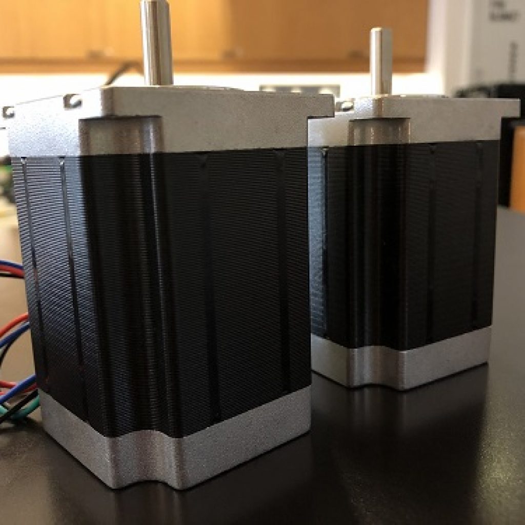
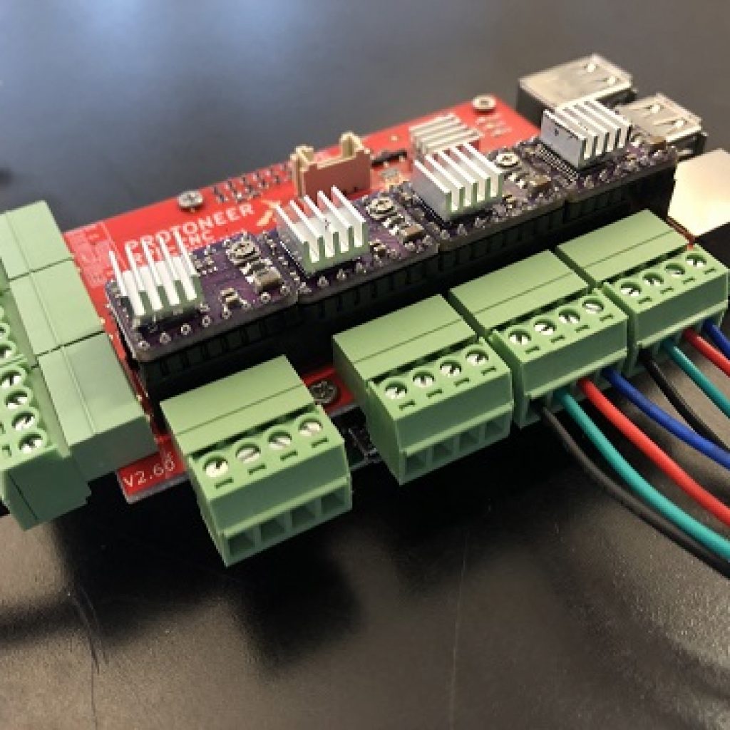
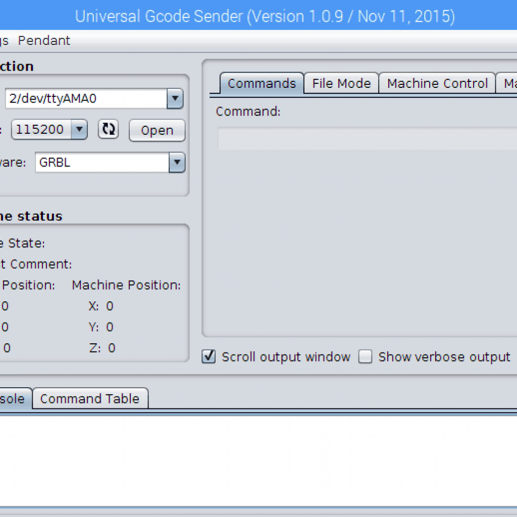
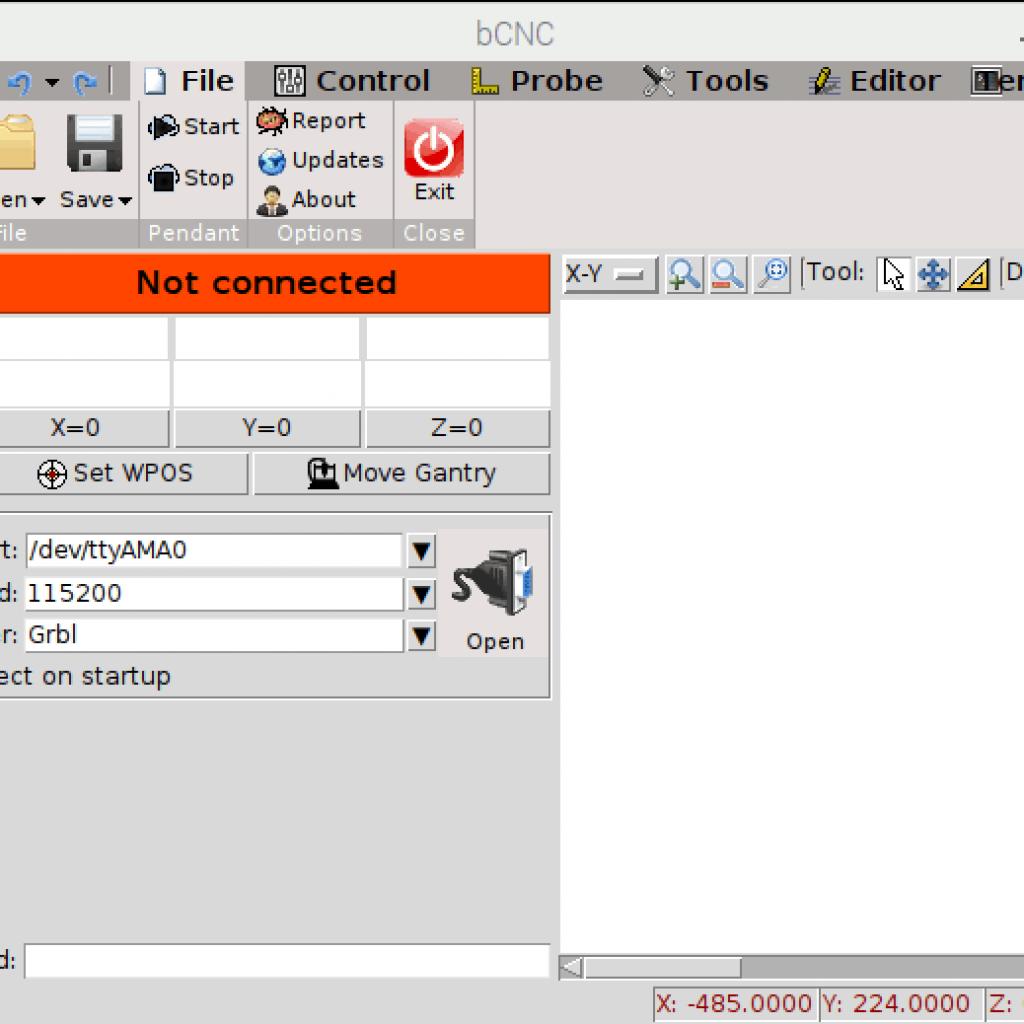
1) The stepper motors connected to the Raspberry Pi and CNC Hat in the background, 2) another view with the final power supply not connected, 3) the spindle and clamp before wiring, 4) the two stepper motors, 5) a better view of the CNC Hat with the purple stepper drivers, 6) Universal G-Code Sender, 7) bCNC
I am happy to say I finished my first milestone for the CNC router. I used an application on a Raspberry Pi to control a stepper motor. A Raspberry Pi is simply a small computer, roughly the size of a credit card. It’s a popular prototyping platform. In this project, it’s the board under the CNC Hat which is optimized to plug directly into and work with a Raspberry Pi. The CNC hat manages controlling the mechanical aspect of the router. In a sense, it acts as a middleman between the Raspberry Pi and the physical movements of the router. With it, there is a streamlined process to translate any of the software into motion. I then opened the connection to the CNC hat through a serial port. The serial port is a software-generated connection that transfers data one bit at a time on the general purpose data pins (GPIO) on the Pi. After that, I did a test run of the key electronics through the Pi, using a power supply and a multimeter to check the results.
Testing and Software
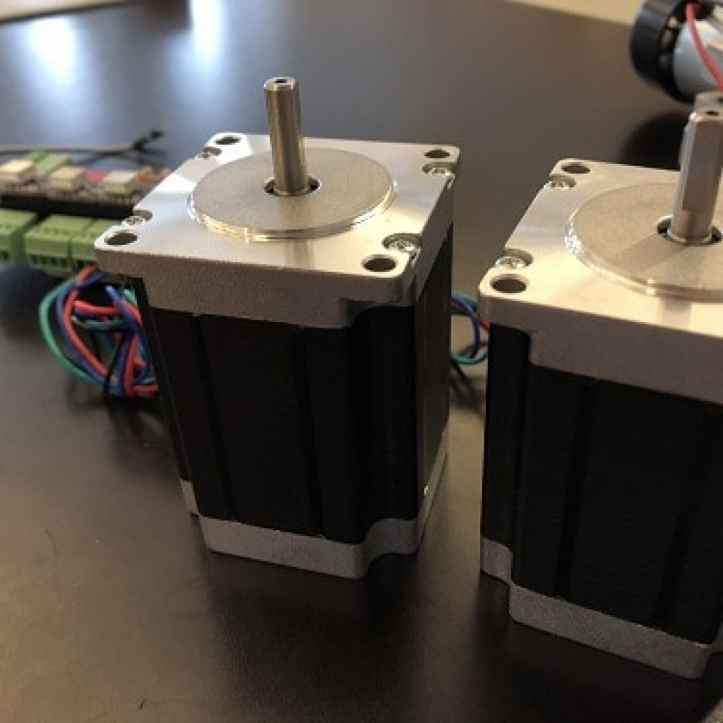
During the test fitting of the electronics, the Pi’s software came in handy via the serial port. I used stepper drivers which are circuit boards designed to plug into the CNC Hat and send the right signals to the stepper motors using external power. Although this could be done without drivers on a breadboard, the drivers replicate a common circuit in a much smaller form factor, streamlining the electronic setup. With the drivers, I was able to drive two stepper motors on 12 volts from an external power supply. Stepper motors are calibrated to know how far to move in a direction, although they may not know where they are when starting or stopping. The reason I needed special drivers to control stepper motors is because stepper motors run on two coils instead of one, like most DC motors use. To use both coils at the same time, the drivers send precise signals at intervals to drive the motor correctly. I used bCNC and the Universal G-Code Sender to send commands to the CNC hat which allowed me to precisely control the motors for the X and Y axes of the router. Both bCNC and the Universal G-Code Sender are relatively basic applications, which take in commands in G-Code, and convert it into the right movements needed of the motors to move the router a given distance. bCNC has especially good documentation and I recommend reading through it if you want to make a similar project. Although I did control movement from the motors, the ratios for accurate movement were not correct. Editing the configuration files in bCNC will be a part of the next step in the electronics to ensure correct units and details are used. Overall, I’m pleased with the progress on the electronics so far. The next step will be fabrication and assembly of the router itself. I’ll mount the electronics as a final step later on.
Starter Project


The default display image displayed left and the fully assembled circuit board above
I started off with a basic project, the MiniPOV 4 kit from Adafruit. The project is relatively simple. It’s a printed circuit board, often referred to as a PCB. It uses an Atmel atmega328p microcontroller. A microcontroller is a chip responsible for controlling and routing signals to digital systems. Here, the microcontroller drives a series of eight LEDs which display a message when moving.