
Final Milestone – Homemade MP3 Player is a Success!


Bill of Materials – PDF: file:///Users/jorsimkovic/Downloads/Starter%20Project%20-%20Bill%20of%20Materials%20-%20Sheet1.pdf
Microsoft Excel: file://localhost/Users/jorsimkovic/Downloads/Starter%20and%20Main%20Project%20-%20Bill%20of%20Materials.xlsx
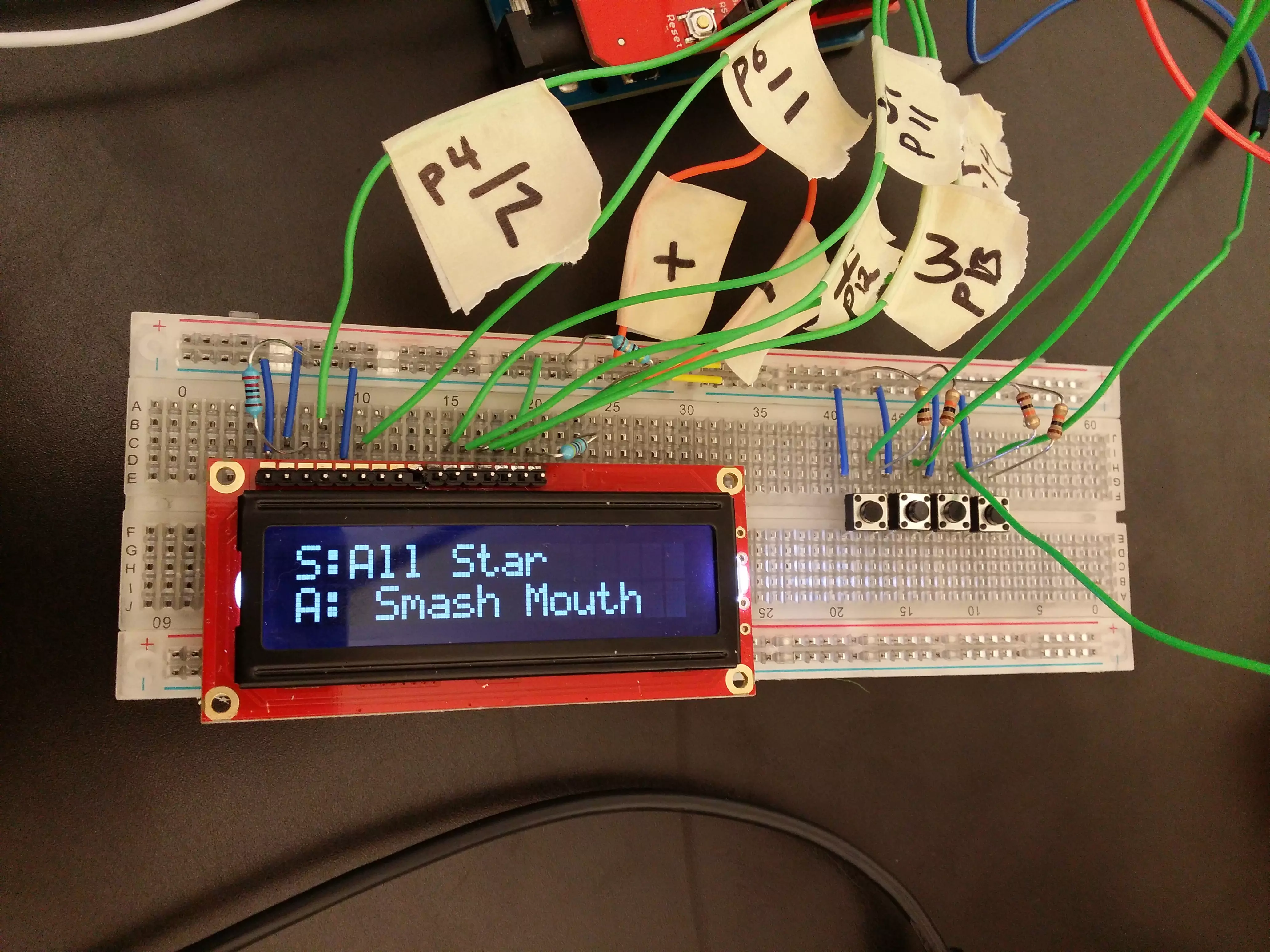
Hey there! I’m Jordan and I’m back with the documentation of my final milestone! So, this time around I’ve added a Liquid Crystal Display, or LCD, which is a screen, to display what song is being played, and 4 buttons which have 4 specific song assigned to each one, respectively. This means that when you push one of the four buttons, a specific song assigned to that button in the code will play. You can view the circuit diagram here. I found that 11 out of the 16 pins are used to set up the LCD. The specific setup can be inferred from the circuit diagram. The way I used the buttons was by inserting them over the middle part of the breadboard, and the pin closest to the LCD to ground, with the further away pin to a 10k resistor to 5 volts. The arduino code can be obtained here. In the code, the names of the songs I used are being printed to the LCD. So if you would like to use your own songs and have them printed to the LCD, you must first put your songs on a SD card, then rename them from track001.mp3 – track004.mp3 (as there is only 4 buttons, you can only play 4 different songs. The most you can play in general is 9 different tracks, and to do this, use the example code mentioned in the previous milestone’s documentation). After, I put the SD card in the shield, and I changed what was being printed to the LCD in the code. To change what was being printed, I changed what was in the parentheses after the command “lcd.print” (ex. lcd.print(“What ever song you would like, but can only put 16 characters per row(horizontally), and there are only 2 columns(vertical)”) ). For further reference, check out this project on and using the wiring diagram program, Fritzing, here. Make sure to give Fritzing a try after checking out the project! The final step for me was to construct a case using SketchUp, a 3d modeling software.
The problems I encountered while completing this milestone include finding that I only had 4 available digital pins with the shield mounted on the Arduino Uno, and how I would be able to use the LCD and buttons with only those 4 digital pins and all 6 analog pins. I found that the LCD requires 6 arduino pins, but only 4 digital pins were available due to the shield requiring 10 specific digital pins. The pins that are available when using Sparkfun’s MP3 Shield are : 0,1,5,10, and all of the Analog Pins. I then found out that an LCD can use analog pins if they are treated as digital pins, which is how I solved the problem. I then used the four open digital pins for the buttons. If you need more pins, you must use a shift register. However, I was able to complete this project without using a shift register. Through the course of the project, I learned how to troubleshoot a project where not enough digital pins are available, and how to treat analog pins as digital pins. Something interesting that I found about adding the LCD and buttons is that they turned a simple project of just uploading a code to a shield, into a unique project of my own.
Milestone 1 – Progress
During the course of my time at Blue Stamp, a “Build Plan” was created which was a plan of how you were going to build your project, and included milestones. As of now, I have completed “Milestone 1”. This milestone was being able to play music on a MP3 Shield by Sparkfun, mounted on an Arduino Uno, by Arduino and distributed by Sparkfun.
The MP3 Shield plays music by using the VS1053B IC Socket to decode audio files (only Ogg Vorbis/MP3/AAC/WMA/MIDI audio files). The audio files are sent to the socket using a “Serial Input Bus”, which is how microcontrollers and SD Cards normally communicate. An SD card is a storage device that work similar to a flash drive. You drag files onto it from your computer, which can in turn be read by an Arduino to produce music if the files put on the SD Card were audio files, which is exactly how the SD Card is used in this project. After decoding the audio file into bits, (the audio file is sent to a DAC, which is a device that converts digitally stored files into analogue signals, making the volume louder and improving the quality. This allows the user to decide which track is going to be played) the file is converted into sound. The decoding is controlled by a serial control bus. When headphones are plugged, they work the same way anytime you plug headphones into your computer. There are a few steps to getting this to work. The first step is to apply headers to the shield, which are components that are soldered into the pinholes on a shield so it can be mounted on top of an Arduino. Once the headers are applied, you will be able to mount the shield on the Arduino. Next, you must format the SD Card, which is changing the type of file the SD Card is. . If it is not in the correct format, the shield will not work. The SD Card must be formatted either FAT16, or FAT32. After the SD Card is formatted, it is time to find some MP3 files to put on the SD Card. To do this(as well as format the SD card), you must put the SD card into your computer(you will need to make sure it is the correct size, and if it isn’t you must use a converter). Once you have done this, place the SD card into the shield. Before you can play music, you must get the most recent libraries of “SDFAT” and “SFEMP3Shield”. You can obtain them here. To install the libraries, place them in the libraries folder of Arduino (you must create this folder if you have not already). The finals step is to run the example code. To open this file, go to: “File” > “Examples” > “SFEMP3Shield” > “Examples” > “FilePlayer”.
Over the course of the project, there were a few problems that were encountered. One of those problems was what type of Arduino microcontroller could be used. The tutorial on Sparkfun says that any Arduino microcontroller can be used. However, if you do not use one of the first three mentioned, you could encounter problems as the sketches (which are the written code in the Arduino compiler) are extremely large, meaning if your Arduino has a maximum sketch size of less than 29,000 bits, you can not run the code. Another problem that can be encountered is that the shield does not come with headers. Though headers are easy to obtain, it takes a while for them to arrive. A disadvantage of this shield is that it can only play a maximum of nine songs, and does not continuously stream. This means that every time a song ends, you must type which song you want into the serial monitor.
My next milestone will be to add buttons and a LCD screen displaying what song is playing.
Starter Project – A Beginning
Hello, my name is Jordan and I am a student at BlueStamp Engineering. My starter project was the MintyBoost, by Adafruit, a charger that can charge a wide variety of phones (compatibility list here) via a USB port.


My finished project contains many different parts that were soldered in the correct place on a circuit board. One category of these parts, or components, are resistors. Resistors affect the current, meaning the intensity of the flow of electrons through the circuit, and the voltage drop across the resistors, meaning that there is not too much voltage at one point. This helps prevent a “short”, or where there is no resistance, meaning the power source is being drained and the parts will overheat. R5 in the MintyBoost boosts the high current capability of the chip that charges the device (diagram (for all components) above). R1,R2,R3, and R4 all help the phone recognize that this is charger. The next components are capacitors. Capacitors help contain the voltage by storing energy. C1 helps stabilize the output voltage of the current into the phone and filters out high frequency noise. C2 stabilizes the chip so it can produce a more precise voltage. The electrolytic capacitors stabilize the output and input voltages during the up-conversion, or when low input voltage from the batteries is converted to a high output voltage into the phone. Diodes are components that are used to make sure the current flows in only one way, as they are polar (meaning they have a specific side for the voltage and a specific side for ground)and need to be put in correctly. D1 is used for just that, making sure the current in the MintyBoost flows only one way. Power Inductors are used to produce voltage and store it, and then convert low voltages to high voltages. The final component is the IC Socket. The IC Socket is used to protect the chip so that you can remove it if you have to.
As a note, the wires connecting to the battery pack provided are stranded-core, meaning there are multiple metal wires in the plastic sheath. This will create problems if the wires from the battery pack are soldered poorly, as the wires will fall out of the soldered hole on the circuit board. It is advised to use a separate battery pack that uses solid-core wires, or where there is one, single wire. Furthermore, a problem will arise if the wires are not clipped, as they will touch and short-out the circuit. To make sure there is no short, check the circuit board and batteries to make sure neither is heating up. Overall, this is a great project for beginners and provides valuable soldering practice.