
Jonah’s BlueStamp Webpage: R/C Hovercraft
My name is Jonah and I am a rising junior at the Trinity School in Manhattan. I chose BlueStamp because I have always enjoyed creating, and wanted to have the freedom to build whatever I want. I chose the MintyBoost for my starter project because I wanted to delve into more advanced circuitry and I thought it was the most practical and useful of the started projects. For my main project I chose the R/C hovercraft because I wanted to make something that would be relatively interactive and something that I would use and enjoy in the future.
I am so glad to have done BlueStamp this summer because I feel it gave me multiple experiences that will prepare me to be an engineer in the real world. The instructors do not simply give you answers, just as when one is an engineer at a real company, they cannot just ask for the answers and be done with it. They require proof of at least three attempts to research it and find the answer. However, they do not disapprove of using google or wikipedia, because those are resources available to everyone all the time. This has enabled me to begin to build a quadcopter on my own, and the experience of knowing what real engineering is like, and the knowledge I have received, will enable me to engineer greater and more complicated projects in the future.
Final Project: R/C Hovercraft:

My main project is the R/C Hovercraft. There are two brushless motors that connect to ESC’s (Electronic Speed Controllers) which power the motors. Then I have two servo’s which are powered through the receiver. The transmitter sends signals to the receiver and turns on the motors. I have Electroluminescent wire that lights up all around the craft. I have some LED’s which are always blinking on and off in a pattern. I have taillights which blink depending on the tilt of the craft.
Modification Video:
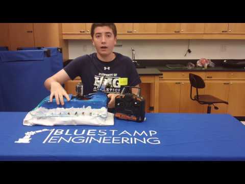
For my completed hovercraft I have made some big modifications since last time. I painted the craft blue and white, and improved some the servos motors for more advanced control over the craft. My biggest new modification is my Mustang-like taillights that are controlled by an accelerometer. When the craft makes a large turn it tilts to the same side, and the accelerometer detects that tilt. Then it tell the Arduino to blink the LED’s on the side the craft is turning on and off in the same pattern as the mustang taillights.
Documentation:
Link to my Bill of Materials, link to my Build Plan.

Link to my CAD Drawing from TinkerCAD
Link to my Arduino Code
Download for schematic of R/C Hovercraft: (I had to use photoshop to get the receiver in, because it is not on Fritzing, so the absent space where the wires lead is where it should be).
The LiPo connects to the ESC’s which shoot current into the motors and then the receiver, through which the servos are powered.

Third Milestone:
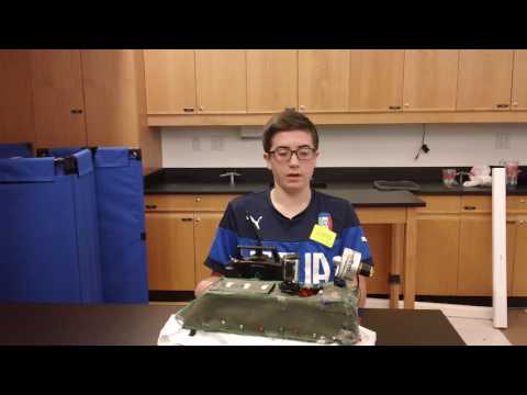
For my final milestone I greatly improved the performance of my hovercraft, making it lighter and more easily controlled. I cut off the side that did not contain anything important and improved the skirt to make it lighter. In addition I added some blinking LED’s on the side and added some EL wire. EL wire is Electroluminescent wire that lights up when AC current is shot through it. This milestone did not take too long, and I will make more advanced modifications using more advanced Arduino coding and an accelerometer. The code for the accelerometer is linked in my documentation section.
Second Milestone:
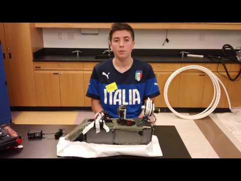
For my second milestone I have fully inserted my electronics into my hovercraft chassis, and now it works. The fan inflates the skirt, which creates an air cushion under the craft. This eliminates most of the friction and so the propellor motor can push it easily. I also attached an action camera which live streams video onto my phone. The propellor motor and the camera are both on servos, so they can turn. I had to saw off the sides of my craft because originally it was too heavy, but now it is light enough. Next I will add some LED’s on the front and the back and code them with an Arduino.
First Milestone:
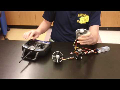
For my first milestone I have completed the full electronic circuit that will connect to my transmitter and can move the hovercraft. The whole circuit is connected to a LiPo (Lithium Polymer) battery which sends current to the two ESC’s. From the ESC’s the current is sent to the receiver which is wirelessly connected to the transmitter, using Tx Rx signals, and then from the receiver current is sent to the servo, so everything is powered. When I move the left joystick down the hover motor which will make the craft float turns on. When I move the right joystick down the propellor motor spins. When I move the right joystick to the side the servo turns. In making this circuit I encountered a few problems. I had to re-solder some wires which were originally not soldered well enough. I also had to figure out how to power both ESC’s directly and not through the receiver, because originally one ESC was powered through the receiver and was not getting enough voltage. Then I had to cut two wires and solder three wires together to get enough current to each ESC. Once I did that everything worked smoothly. Next I will put this circuit inside my hovercraft and then I will be done. After that I will make modifications to make the hovercraft cooler before the program ends.
Starter Project: MintyBoost Boost Converter
MintyBoost video:
For my starter project I built the MintyBoost phone charging boost converter. It takes 3.3V from the batteries and converts them into 5V with which to charge your phone. The MintyBoost works by using an inductor. When the minty boost is turned on there is a circuit with the battery and the inductor, which has very little resistance. Due to the small resistance there is a lot of current flowing through the inductor. The way the inductor is made, there is a metal coil wrapped around the wire. When current is shot through a metal coil there is a magnetic field created. When this circuit has generated a large enough magnetic field, a switch inside the booster chip opens, including the load (your phone) into the circuit and adding lots of resistance. The added resistance should force the current to change, but a basic function of an inductor is that it resists current change. This results in the inductor opposing the change by expending its magnetic field towards the load, increasing the voltage in the circuit, but not changing the current. The switch then closes, rebuilds the field, and opens again adding more voltage. This opening and closing repeats itself over and over until the voltage has been raised to 5v. When it hits 5V the sense pin in the booster chip notices this and sends a signal for the switch to stay open. However, when your phone charges it saps some of that voltage. When voltage is lost the switch has to open and close again, and this process is repeated so that the voltage is maintained at 5V and it charges your phone.
In making my project I hit a few roadblocks that I had to overcome. First I had two wires come unsoldered and I had to put the soldering iron back to the solder and then insert the wires again to connect them. After that I had to add more solder to secure the joints further. I also wanted to find a way to connect a switch so that I could save some battery power. I cut one of the wires connecting to my battery and then attached the switch. Then I had to find out which of the three prongs on my switch to attach my wires to, and I figured that out using a multimeter.