Jonah B.
I am Jonah, a rising senior at SAR High School. For my main project, I am building a 3D scanner using “Qlone” scanning software, CAD models that I designed using “Autodesk Fusion 360” (3D modeling software), hardware sourced from hackster and my own “Arduino” code. My project will use an iPhone to scan, compile and then convert a 360-degree video of an object into a “.stl” file which can be 3D printed. I chose this project because it combines a breadth of engineering disciplines, including software, firmware, 3D modeling, and circuitry. I am the first BlueStamp student to build a scanner. Accordingly, there is a lack of precedent which enables me to define and refine the scope of my project as I build. There is beauty in the uncertainty of not fully knowing where the project may lead.
Engineer
Jonah B.
Area of Interest
Entrepreneur Engineer or Professor (Engineering, Philosophy, Math or Physics)
School
SAR Highschool
Grade
Incoming Senior
Final Milestone
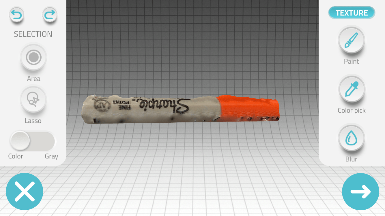
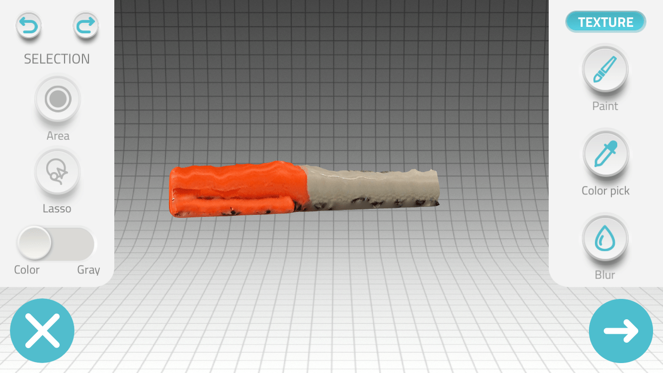
Successful Scan of a Sharpie
For my final project, I built a 3D scanner that can use an iPhone to scan objects for 3D printing. The apparatus mechanically spins the object for photographing and then compiles the images into a .STL file which can be sent to a 3D printer for printing. This is similar to how a photocopier works. A 2D piece of paper is scanned, the scan is compiled and the printer outputs a replica. I did not design the software to compile the 3D image, but built all of the hardware and wrote the code to facilitate the scanning.
First, I built a turntable with gears to rotate the object so that the iPhone camera could remain still as it scans (milestone one). I then automated the rotation of the turntable using a stepper motor that spins at an optimal speed to take clear pictures (milestone two). I then built an apparatus to scan the image at different angles and designed a six-button controller for my motors. The apparatus can raise and lower my iPhone using a DC motor and tilt my iPhone using a servo motor (milestone three).
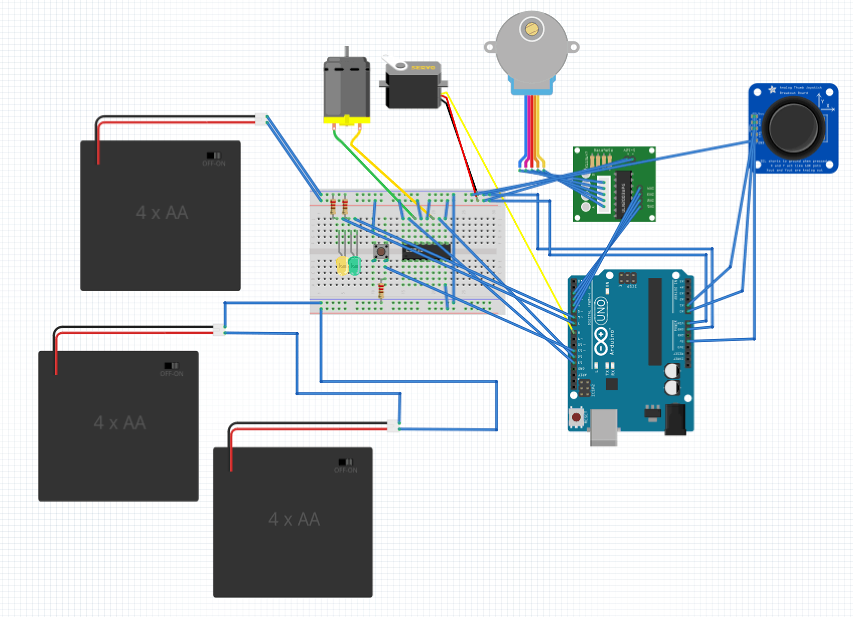
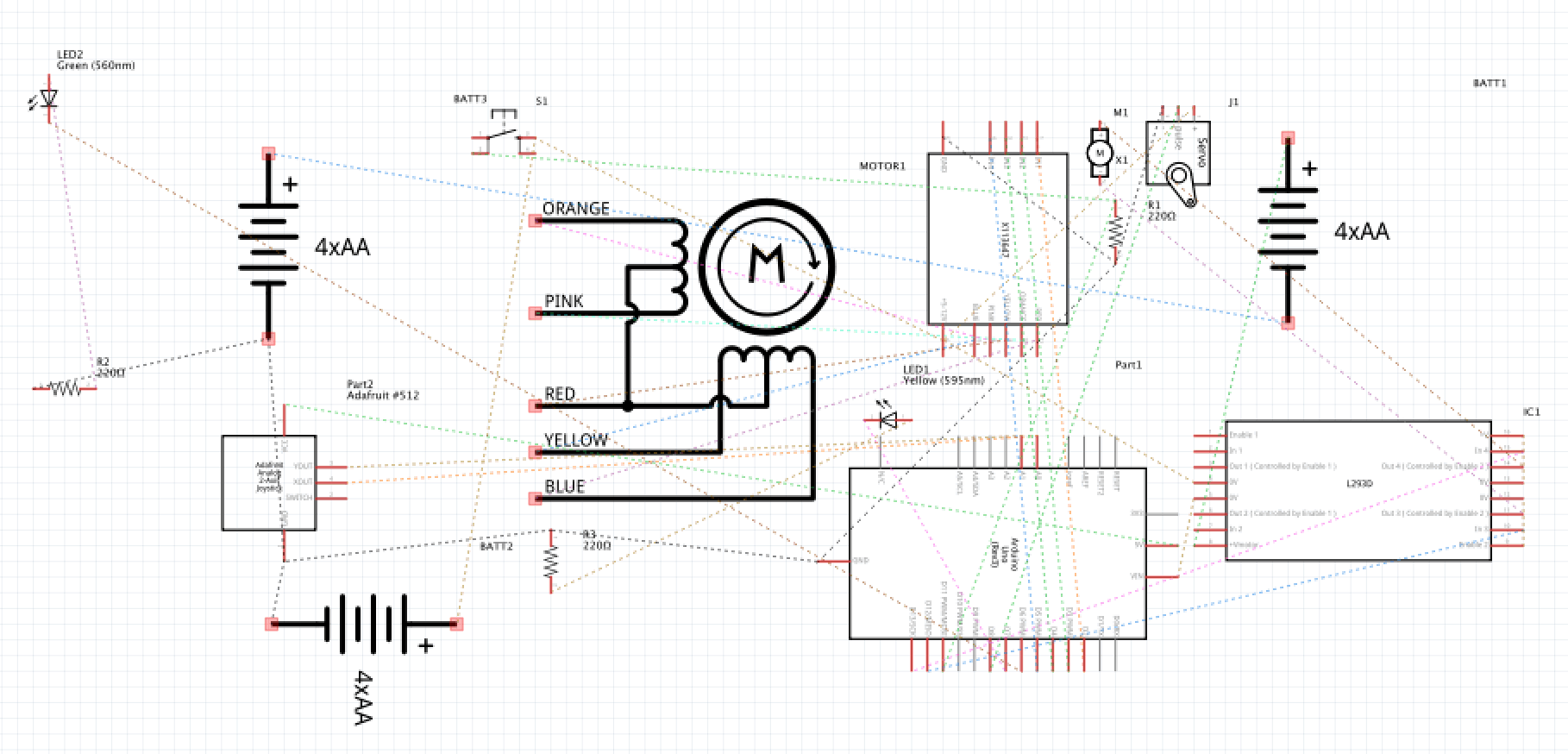
For my final milestone, I added a modification to the controller. Rather than having six buttons control my project, I introduced a joystick with two modes that uses a button to toggle between the modes. Different color LEDs turn on to represent the mode of the Joystick. Each mode has four different position (up, down, left and right) that initiates a command. Each of my three motors has an axis (X or Y) of one of the joysticks modes devoted to its clockwise and counterclockwise rotation. For example, pushing the joystick up in mode one causes my iPhone to tilt up. In mode two, one axis is left unused as I did not need to utilize the fourth motor.
The coding for the joystick was difficult. A joystick is composed of two perpendicular potentiometers that can read 1024 different values. In order to code for my joystick, I treated each potentiometer as a graphical axis: X and Y. I made the intersection of the potentiometers the origin. The value for the center of each potentiometer was approximately 512 so I used mathematics to equate the origin with zero and then convert every value to a number relative to the origin. For example, the 513 value on the X-axis became the number one. Since I wanted my Arduino to only spin one motor at a time, I had to make sure that diagonal movements on the joystick did not spin two motors. In order to prevent this, I turned my joystick’s location into a vector quantity. My code would figure out which direction the joystick was most closely pointing to and only perform that function. Also, when the joystick was in the center, the Arduino would stop spinning the motor. Unfortunately, voltage spikes can affect the values of the potentiometer. The microcontroller may read the origin as being a separate value. In order to account for the error, I programmed the joystick so that it would only command a function if the vector magnitude exceeded a certain amount. This left an imaginary circle in the middle of my artificial plane in which the joystick would perform no functions.
My biggest challenge for this milestone was that my servos would burn out after operating correctly. After a few days of problem-solving, I discovered that I had my servo connected to a non-PWM pin. PWM pins send quick signals which the servo needs. Non-PWM pins send current for a little bit longer which slowly destroyed the servo motors. This explained why my servos would work for a little bit of time but then burn out. I corrected the issue by switching the type of pin utilized.
The joystick modification taught me about complicated coding and nuances in circuitry.
Reflection
BlueStamp was my introduction to the fascinating world of engineering. I arrived with a passion for math and physics but had not yet had an opportunity to intensely apply that knowledge to an ambitious real-world project. The BlueStamp experience exceeded my every hope and expectation. It cemented my deep interest in engineering and exposed me to a wide-range of disciplines that helped me focus my future ambitions. By participating in the program, I received hands-on experience in computer science (e.g. coding my Arduino), electrical engineering (e.g. designing circuits), mechanical engineering (e.g. 3D modeling, using power tools and improvising with everyday objects to solve challenges), web development (e.g. designing and developing content for my personalized website) and project management (e.g. phased development and benchmarking).
I particularly enjoyed the engineering thought process of breaking down problems into the problem’s fundamental components. Computers know nothing, so coding requires describing actions from square one. I could not just tell my computer to make a motor spin counter-clockwise by moving my joystick towards the left. Instead, I had to consider questions such as what causes a motor to spin? How would a computer know the position of my joystick? This methodology of breaking down processes to their fundamentals and constructing logic tables will be helpful to me in all areas of my life. It will also help me turn abstract ideas into practical reality.
Perhaps most importantly, engineering has trained me to handle frustration and overcome failure. Rarely, does something initially work as intended and even diagnosing the problem may take an extraordinary amount of time. Sometimes, the issue may be as simple as a wire that does not conduct properly or a code that is missing a semicolon (yes, I encountered both of those problems). I learned to actually embrace the process and realized that in the pursuit of finding the mistake, I discovered opportunities to make even unrelated improvements, remove inefficiencies and learn alternative approaches. This was certainly true as I scoured my programming code or carefully checked my circuitry for a particular problem. I discovered better ways to program and better ways to wire. And when a 3D model did not print properly, I discovered the powerful capabilities of CAD software such as the ability to put virtual parts through diagnostic tests. My biggest challenge in this regard was my entire Arduino board shorting and my 3D model melting. Rather than quitting in despair, I redoubled my efforts (and my late-night hours) and found solutions, including rewiring my circuitry and utilizing everyday items, such as the inside mechanism of a drawer, to supplement the functions of 3D components. I developed the skill of growing from challenges and seeing initial failures as a step towards ultimate success. Success felt significantly more rewarding after personal perseverance.
I am very proud of my accomplishments and growth at BlueStamp. The breadth of what I learned in the past few weeks only made me more excited about my future in engineering and my ongoing development of the life-skills for success. As I enter my senior year of high-school, including a challenging course load of related AP courses (e.g., Computer Science, C Physics and BC Calculus), I have feel more confidence in my skills and I am determined to apply my knowledge to the real world.
Code for Final Project
https://github.com/jonahb27/3D-Scanner/blob/master/joystick-control-stepper-servo-and-dc.ino
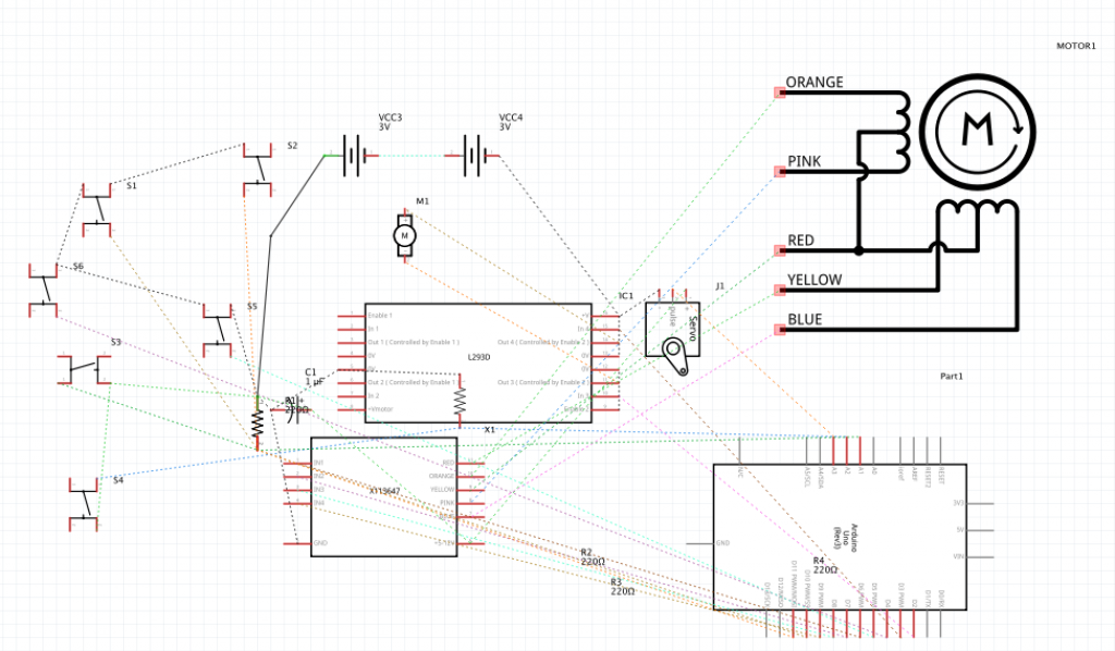
Circuitry for Final Project
Materials (with links)
28BYJ-48 ULN2003 5V Stepper Motor + ULN2003 Driver Board for Arduino
Towerpro MG996R Servo 25T 10kg / 0.20sec / 55g
Drillpro 12-24V Mini Hand Drill Bits DIY Lathe Press 555 Motor Chuck & Mounting Bracket
Pushbuttons, LEDs, and Resistors
Adafruit Dual H-Bridge Motor Driver for DC or Steppers – 600mA – L293D [ADA807]
KY-023 PS2 Game Joystick Axis Sensor Module for Arduino AVR PIC Mega UNO
8 AA Battery Holder with Snap Connector 12V / 9.6V by Corpco
Third Milestone
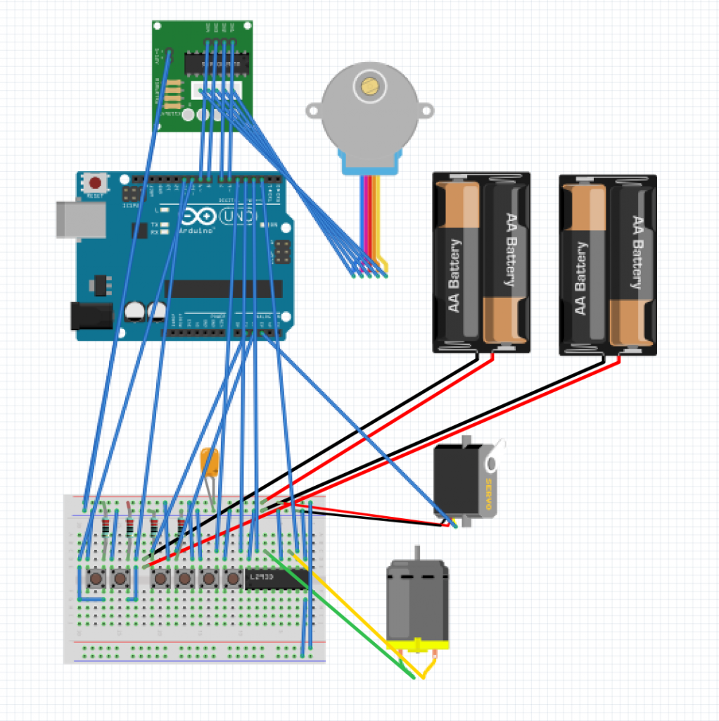
For my third milestone, I automated the iPhone positioning process for my 3D scanner by creating a movable iPhone holder. Prior to this automation, I positioned the iPhone with my hands. Since human hands are not stable, the 3D image rendered was blurry. The new iPhone holder is composed of two motors, a 180-degree servo motor for tilting my iPhone and a 18V DC motor connected to a L293D motor driver for raising and lowering the phone. The mechanism is controlled by six buttons which trigger clockwise and counterclockwise rotation: two for each of the three motors in my project (the two new motors plus the stepper motor that rotates my turntable). The coding for the buttons was challenging because I had to make sure that conflicting commands from separate buttons were disregarded.
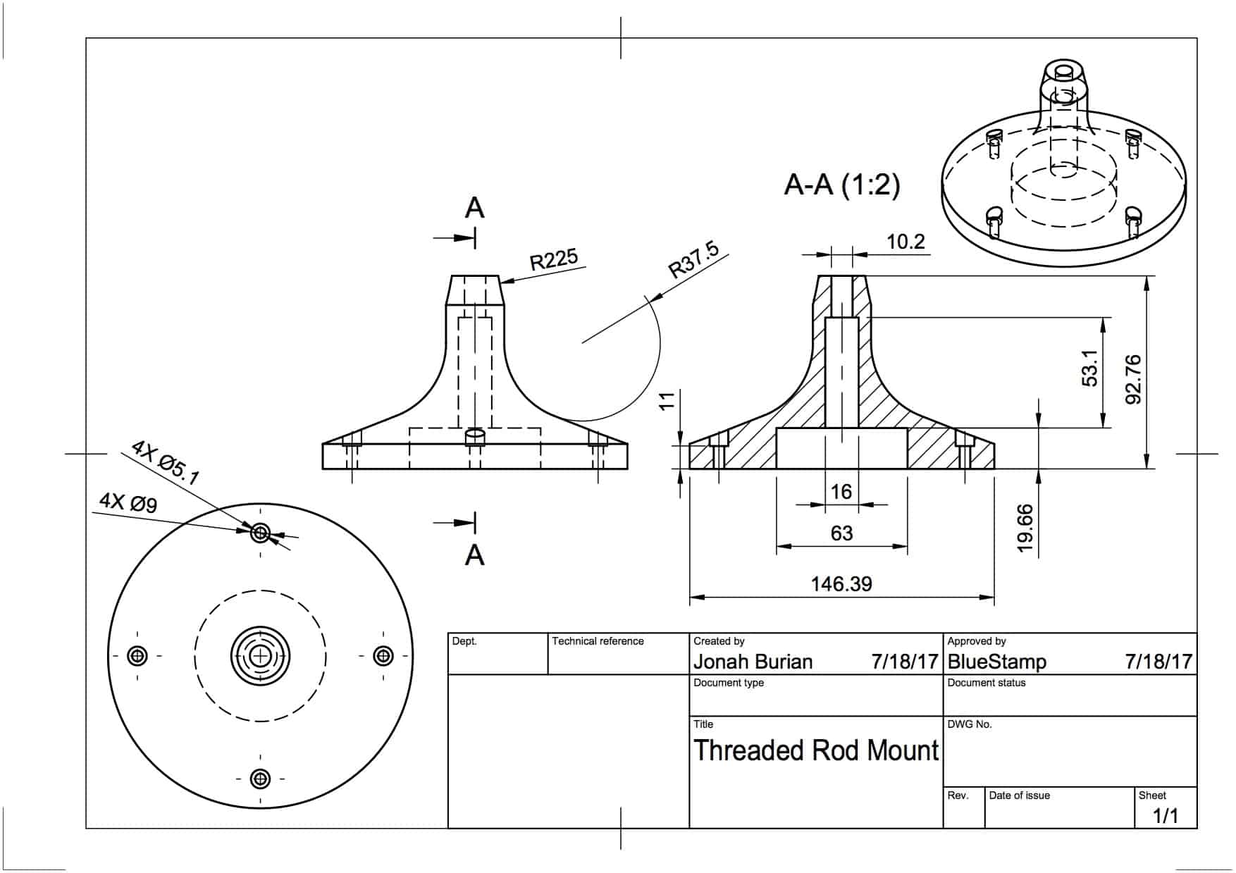
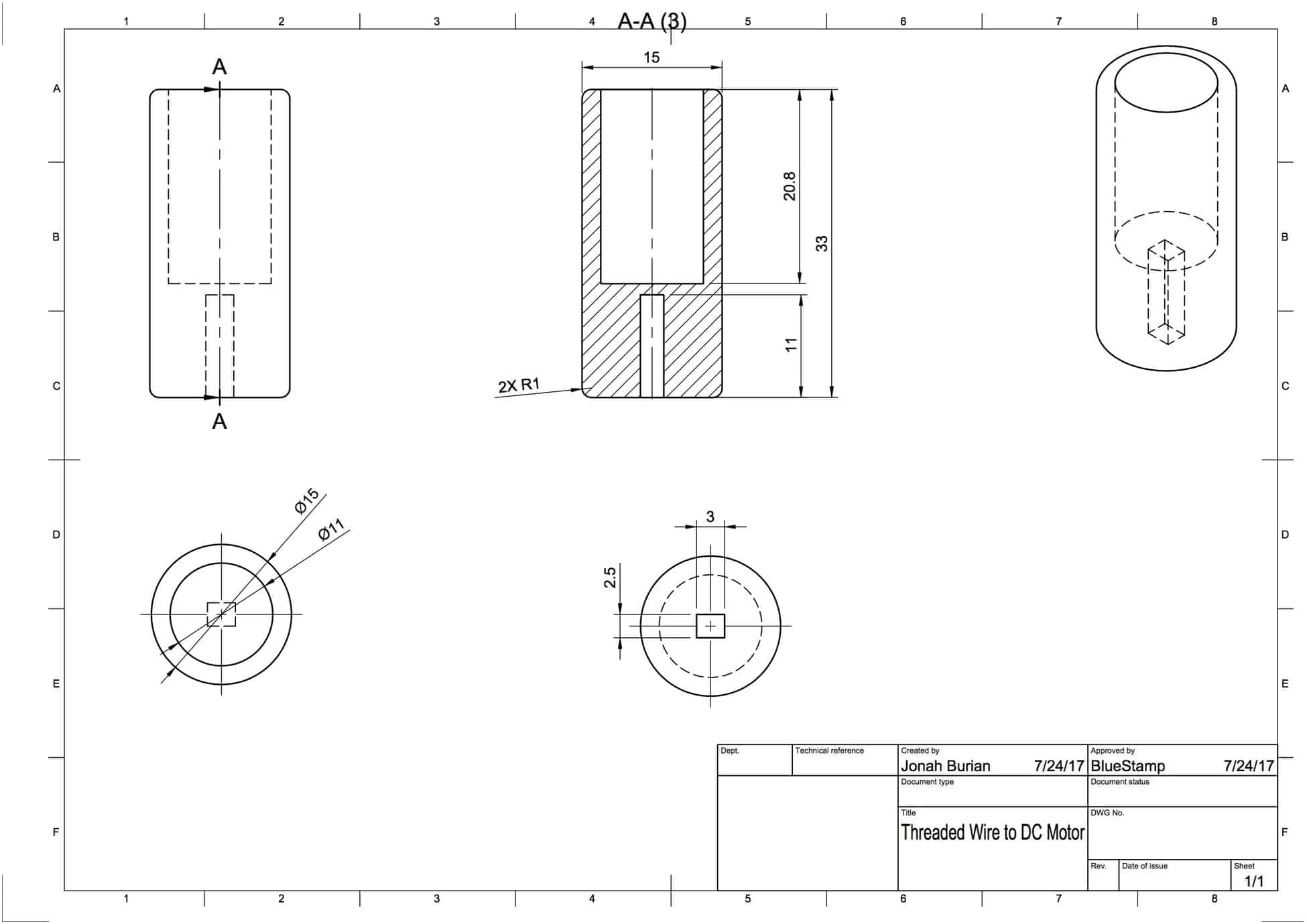
The mechanics behind the vertical axis movement was inspired by 3D printers. A threaded wire, which looks like a giant bolt, is rotated by a motor with a lot of torque. Attached to the threaded wire is a bolt that is connected to a stable item which prevents the bolt from spinning. As a result, when the threaded wire rotates, the bolt must go up or down depending on the direction of the threaded wire’s rotation.
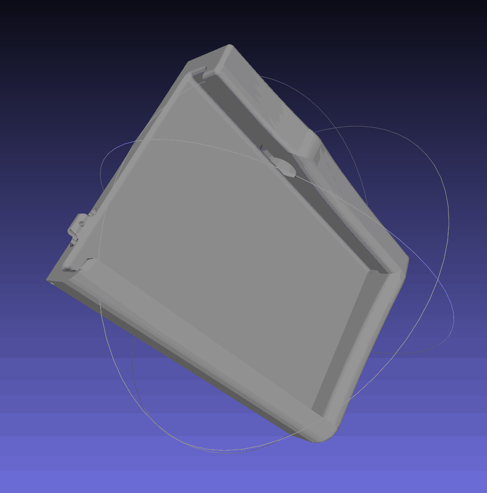
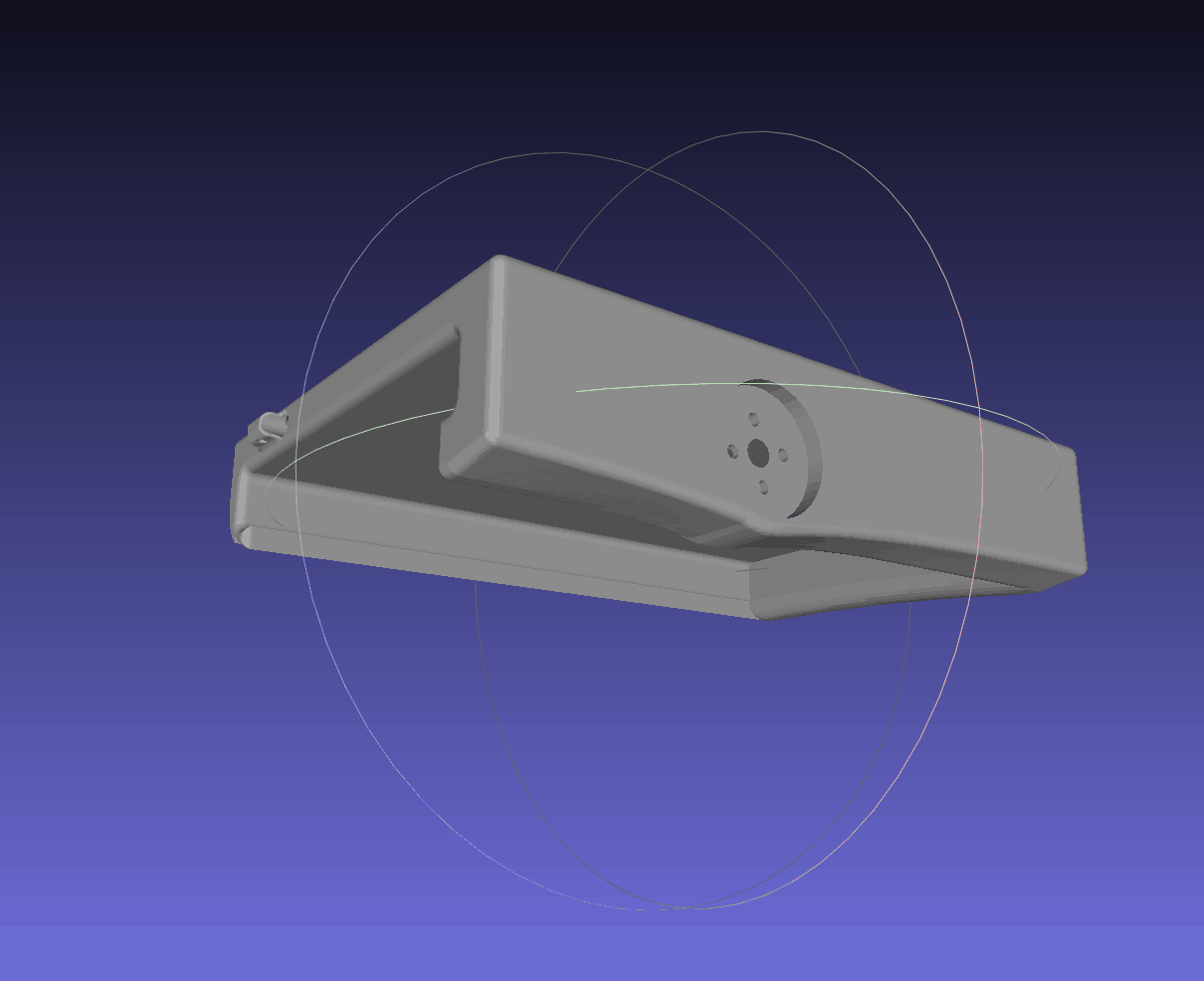
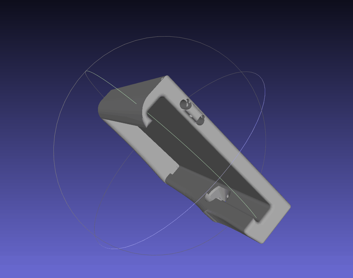
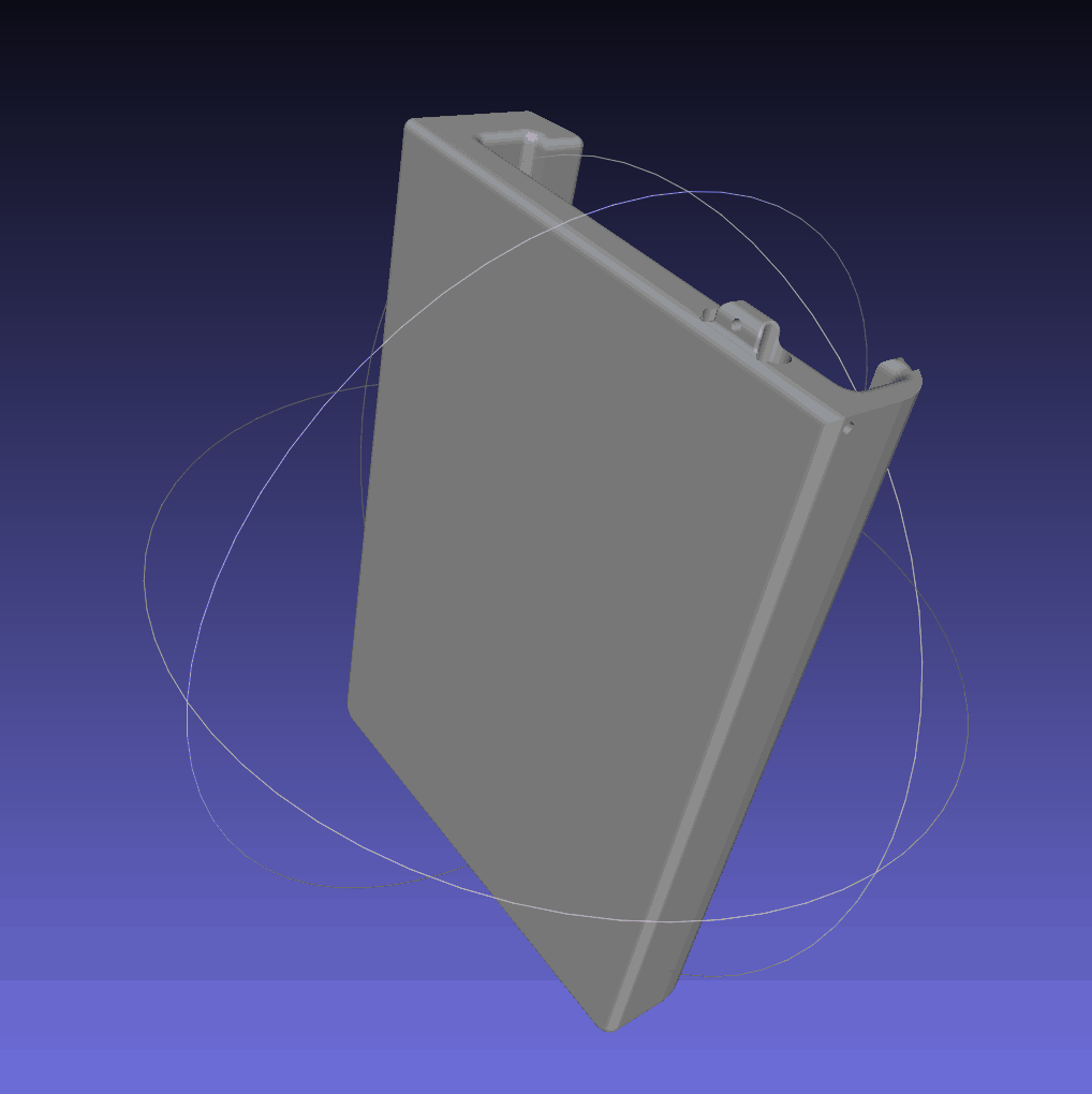
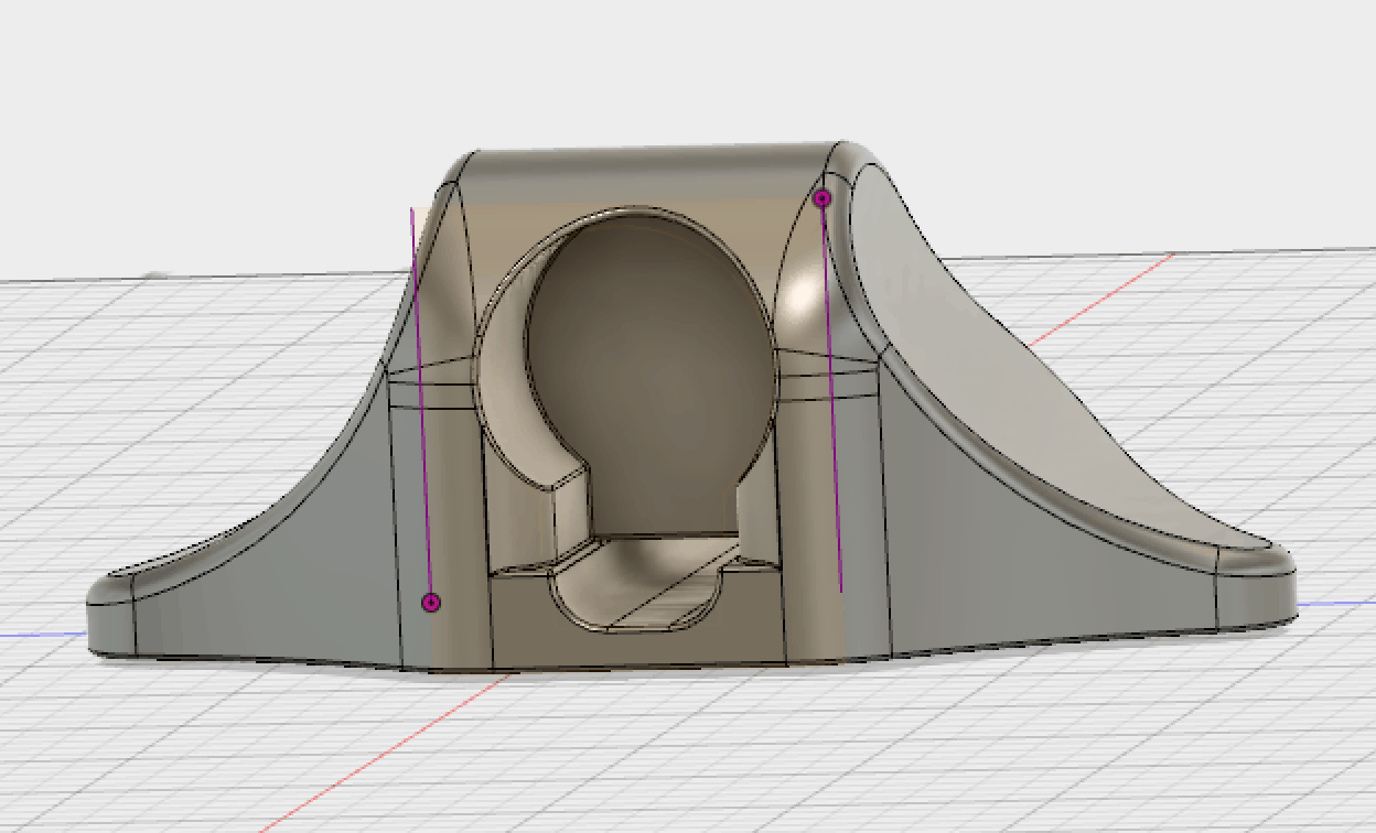
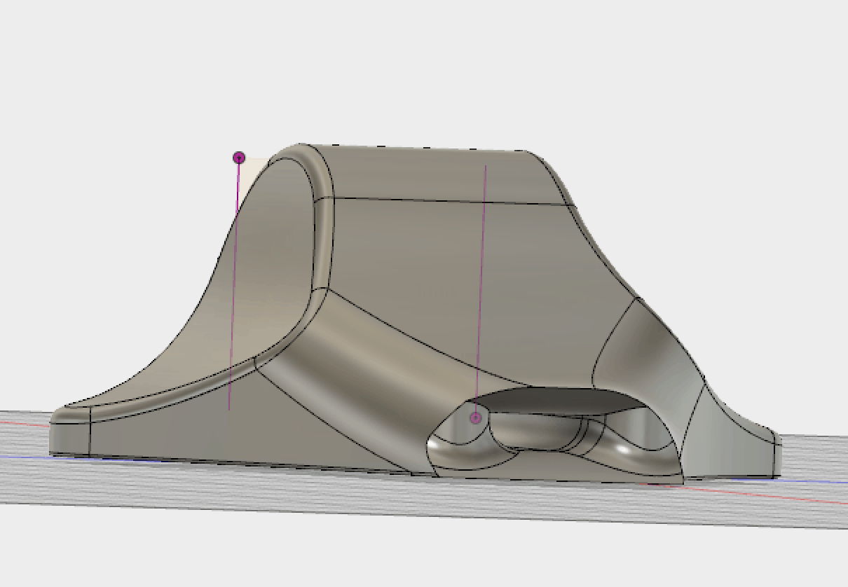
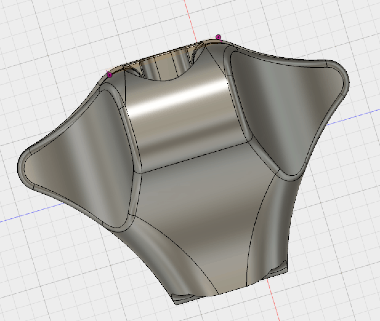
For this milestone, I learned how to 3D model and dimension models using Autodesk Fusion 360 software. I designed numerous components from scratch to construct my third milestone (e.g. motor mounts, iPhone mount). Unfortunately, after waiting days for all the components to print, an accident involving a heat gun melted most of my parts. Since I was short on time and could not reprint the parts, I had to improvise with everyday objects (e.g. the mechanism for a drawer, acrylic slabs) to replace the tasks of my modeled parts. My biggest challenge became mounting the threaded wire to my DC motor and positioning the stable item to prevent my bolt from spinning. The part had to be parallel, with barely any margin for error, for the mechanical task to work.
Completing my third milestone taught me a lot about mechanical engineering since I learned skills such as 3D modeling, using power tools, improvising with everyday items and creating dynamic parts.
Code for Third Milestone
https://github.com/jonahb27/3D-Scanner/blob/master/_6_button_dc_stepper_servo.ino
Circuitry for Third Milestone
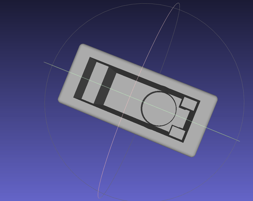
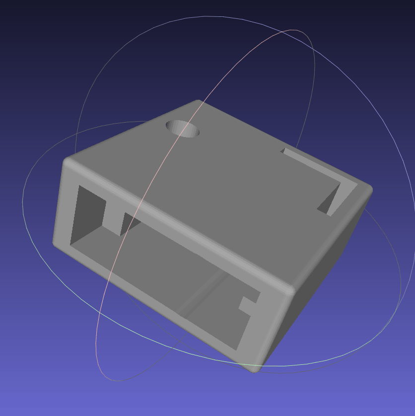
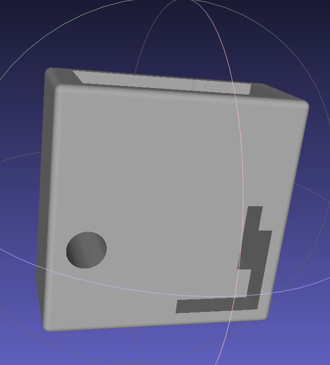
3D Models using Autodesk Fusion 360
PDF Dimensioned Schematics of my CAD Models (with links)
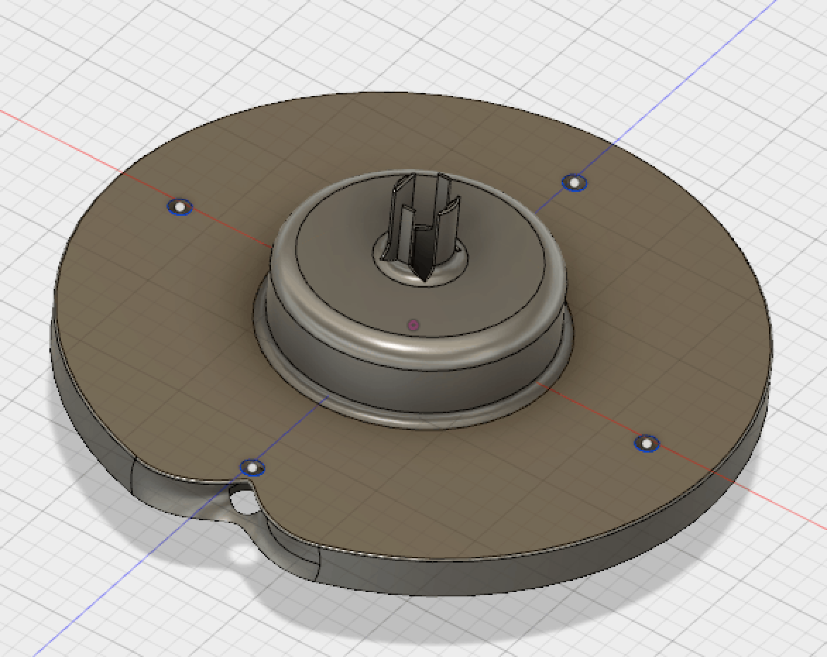
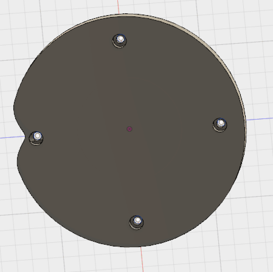
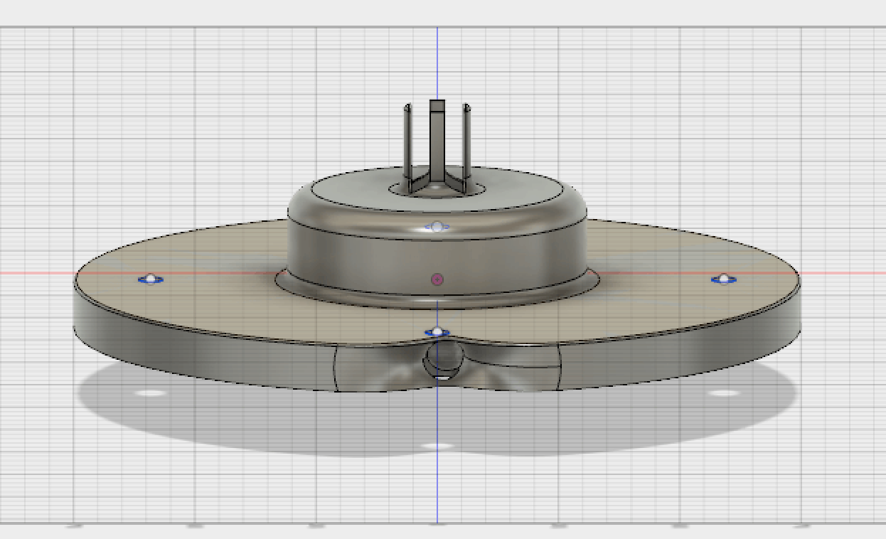
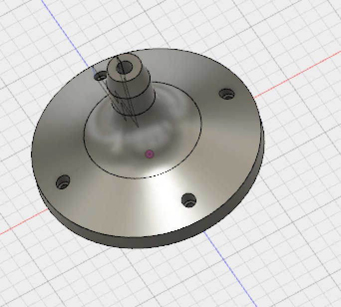
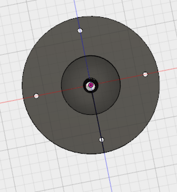
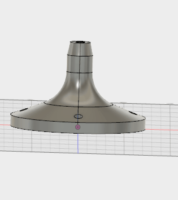
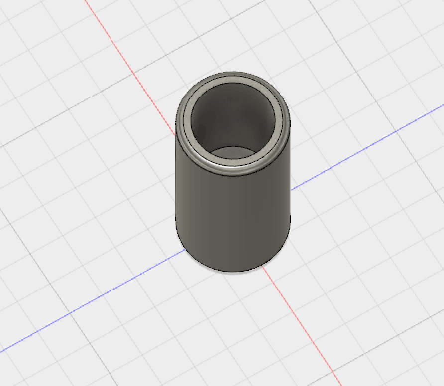
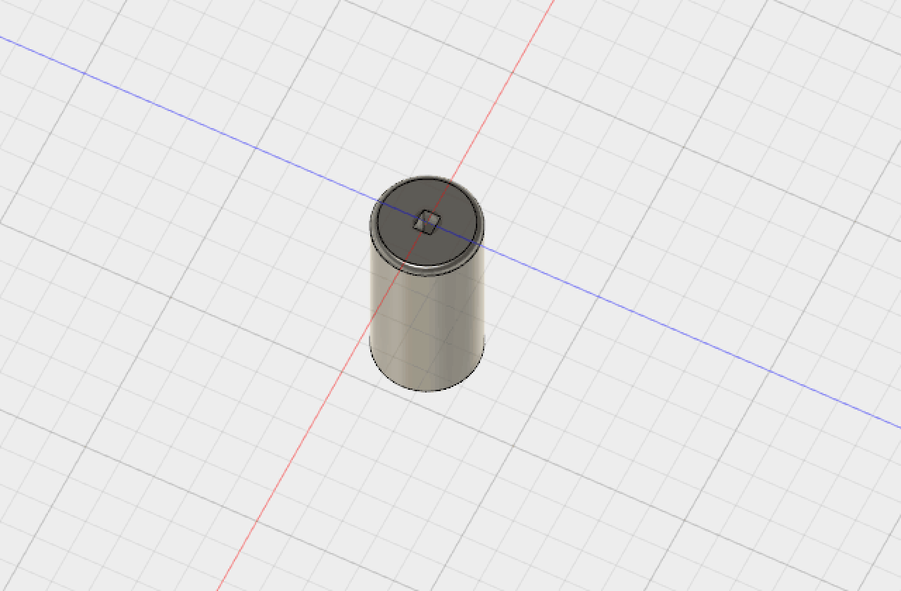
3D Models Photos Autodesk Fusion 360
iPhone Holder
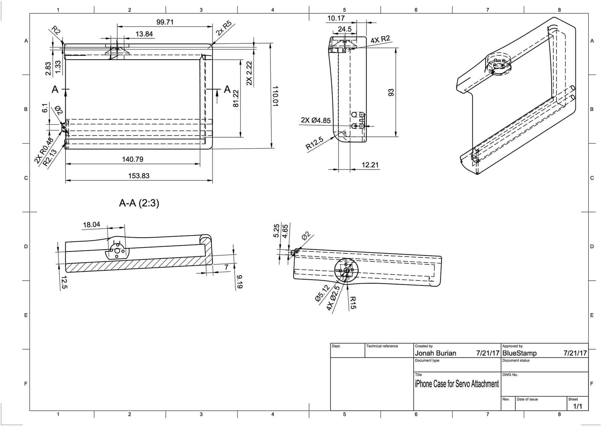
iPhone Clamp

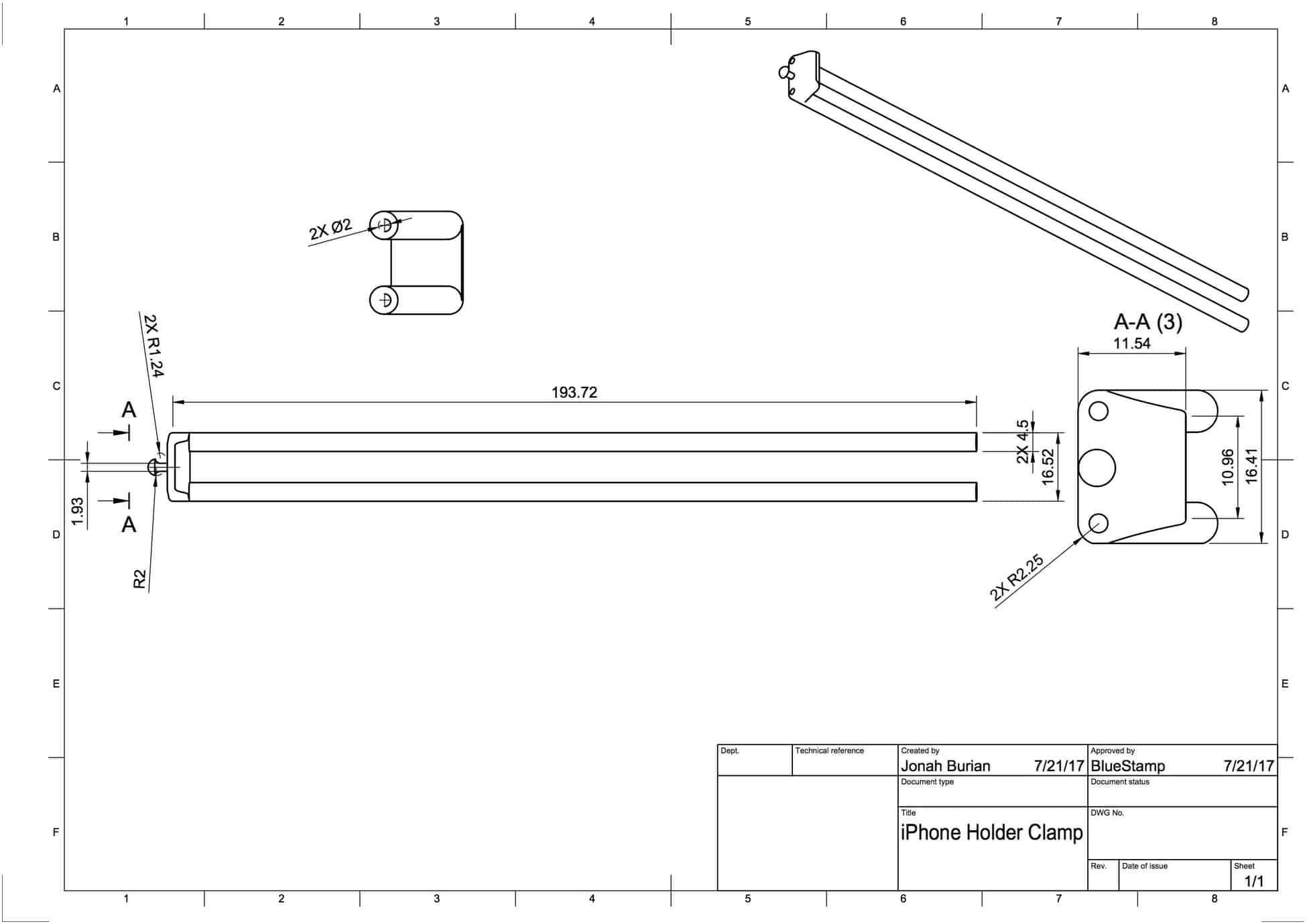
Stepper Motor Holder
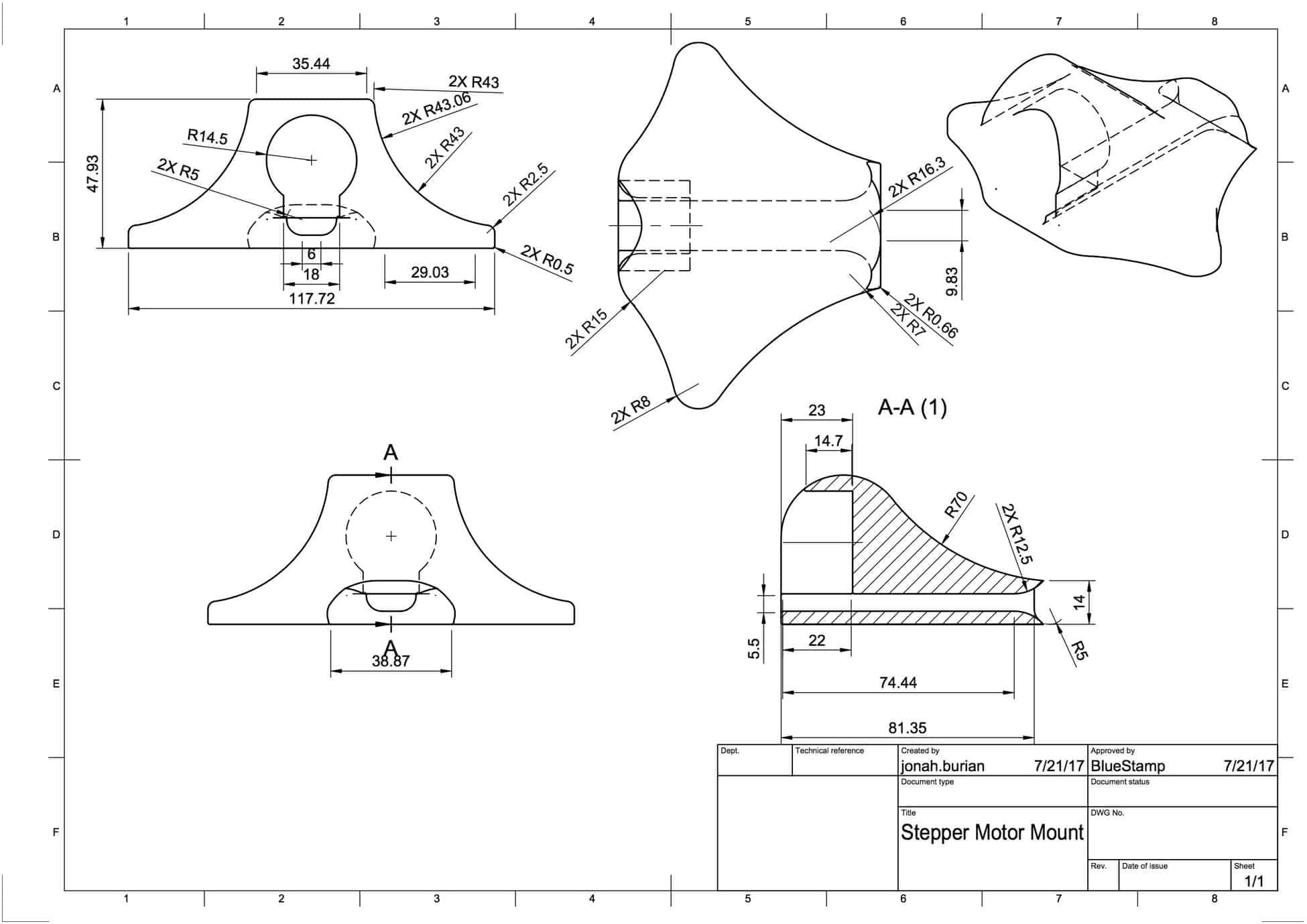
Servo Holder
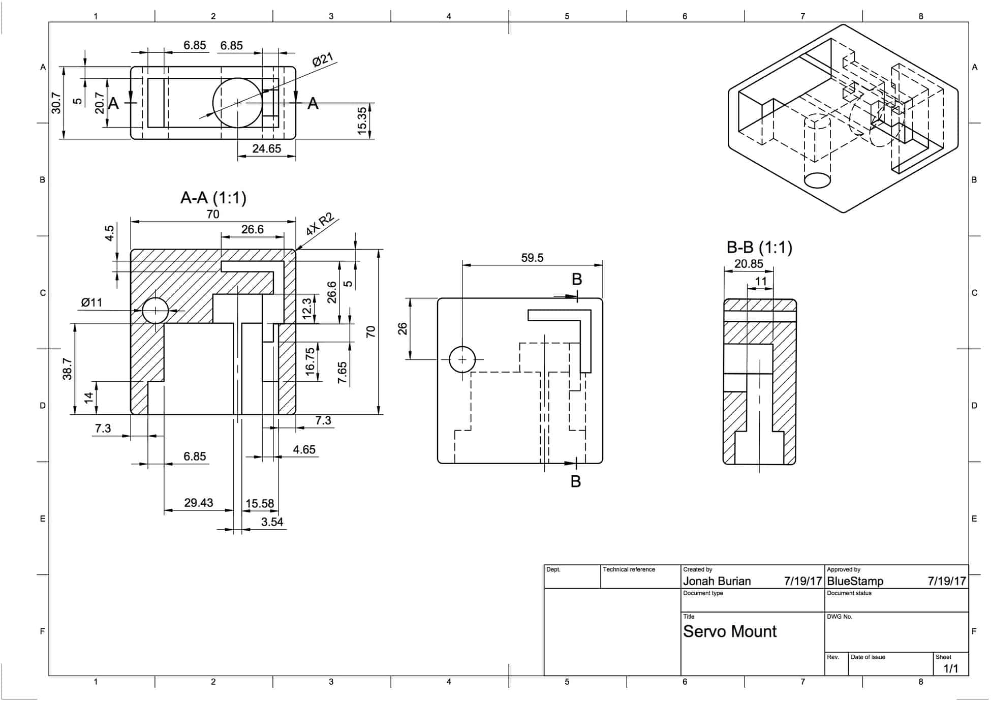
DC Motor to Mount
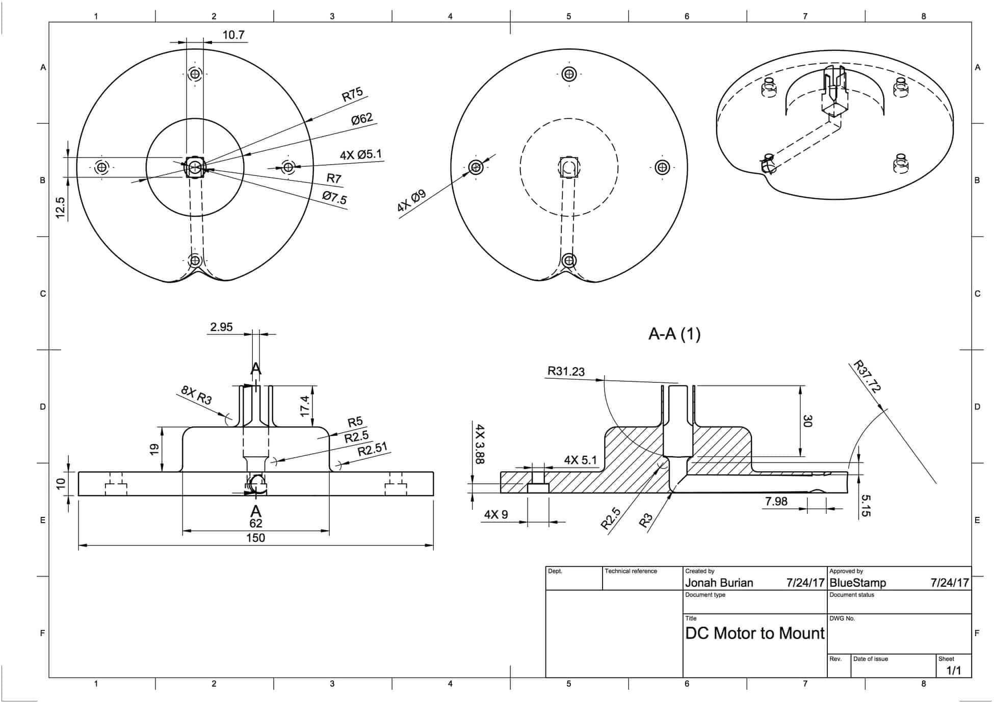
DC Motor to Mount Case
Threaded Wire to DC Motor
Second Milestone
This is the function I wrote for the stepper motor's clockwise and counterclockwise motion.
void turnA ()

{
boolean motorOnA = HIGH;
switch (_stepA) {
case 0:
//Serial.println ("aa");
digitalWrite(Pin0, LOW);
digitalWrite(Pin1, LOW);
digitalWrite(Pin2, LOW);
digitalWrite(Pin3, HIGH);
break;
case 1:
//Serial.println ("bb");
digitalWrite(Pin0, LOW);
digitalWrite(Pin1, LOW);
digitalWrite(Pin2, HIGH);
digitalWrite(Pin3, HIGH);
break;
case 2:
// Serial.println ("cc");
digitalWrite(Pin0, LOW);
digitalWrite(Pin1, LOW);
digitalWrite(Pin2, HIGH);
digitalWrite(Pin3, LOW);
break;
case 3:
// Serial.println ("dd");
digitalWrite(Pin0, LOW);
digitalWrite(Pin1, HIGH);
digitalWrite(Pin2, HIGH);
digitalWrite(Pin3, LOW);
break;
case 4:
// Serial.println ("ee");
digitalWrite(Pin0, LOW);
digitalWrite(Pin1, HIGH);
digitalWrite(Pin2, LOW);
digitalWrite(Pin3, LOW);
break;
case 5:
// Serial.println ("ff");
digitalWrite(Pin0, HIGH);
digitalWrite(Pin1, HIGH);
digitalWrite(Pin2, LOW);
digitalWrite(Pin3, LOW);
break;
case 6:
// Serial.println ("gg");
digitalWrite(Pin0, HIGH);
digitalWrite(Pin1, LOW);
digitalWrite(Pin2, LOW);
digitalWrite(Pin3, LOW);
break;
case 7:
// Serial.println ("hh");
digitalWrite(Pin0, HIGH);
digitalWrite(Pin1, LOW);
digitalWrite(Pin2, LOW);
digitalWrite(Pin3, HIGH);
break;
default:
digitalWrite(Pin0, LOW);
digitalWrite(Pin1, LOW);
digitalWrite(Pin2, LOW);
digitalWrite(Pin3, LOW);
break;
}
if (dirA) {
_stepA++;
} else {
_stepA--;
}
if (_stepA > 7) {
_stepA = 0;
}
if (_stepA < 0) {
_stepA = 7;
}
delay(1);
}
For my second milestone, I automated the spinning for my turntable utilizing a 28BYJ-48 stepper motor and two push buttons to control clockwise and counterclockwise motion. This modification was necessary because when I previously cranked the turntable, the rendered 3D model was blurry and inconsistent.
A stepper motor is a brushless DC electric motor that breaks down 360 rotation into equal increments called “steps”. Surrounding the motor’s main gear is “toothed” electromagnets. To make the motor spin, the magnets must be coordinated to receive electricity. This produces a B-Field that attracts the “teeth” to the main gear. The stepper is connected to a driver which betters the stepper’s response to inputs.
For this milestone, I learned how to code in Arduino, debug code, use a serial monitor, design circuits and navigate open source material. In my code, I set the stepper motor as an output and the push pins as inputs. I created two functions using “for” loops for clockwise and counterclockwise motion. I then programmed my buttons to trigger the functions.
At first, my code did not work so I diagnosed the issue by having my Arduino print information to the serial monitor. I discovered that the buttons were not inputting information properly due to a circuitry issue that was sending current backward. I solved the problem by changing the way my code interpreted the input.
For my third milestone, I plan on automating my iPhone scanning process to produce an even clearer 3D image.
First Milestone
For my first milestone, I successfully built a turntable upon which objects can be scanned for 3D printing. Ironically, I built the turntable itself entirely from 3D printed parts. I obtained part designs from hackster and carefully printed, filed and assembled each of the components (eg., gears). The filing was necessary as I did not anticipate the amount of tolerance required for parts to properly fit together. I learned that the 3D printer was not exact because the material available (polylactic acid) slightly expanded during the printing process. Accordingly, for a part to fit snugly into a hole, I needed to anticipate that the hole would shrink and the object would expand. Going forward, when I design and dimension parts, I will anticipate and calculate the necessary tolerance.
At this first stage, the turntable needed to be manually cranked with a handle (I will automate it for my next milestone). I found an app called “Qlone” which uses an iPhone to 3D model objects that spin at a specific rate. In order to increase the app’s precision, I designed a mat with a QR-like pattern to act as my constant in the scan. I tested the app by standing a key on my turntable using wire. Unfortunately, the 3D model was blurry and reflected inconsistencies due to the manual cranking. I, therefore, converted the image into an STL file and proceeded to edit the scan on the 3D software, “meshlab.” First, I removed the wire from the scan. Then, I found a third party software which enabled me to smooth out the interior and exterior of the 3D modeled key. When fully edited, I converted the “meshlab” file back into a .”stl” file. I was then able to successfully 3D print a rough replica of my key.
Starter Project
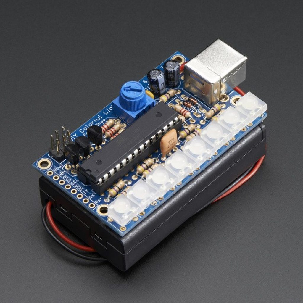
My starter project is a Mini POV, which stands for “persistence of vision.” The device takes advantage of an optical phenomenon where human eyes can see images in a single spot even if the object producing the image is moving. LED’s blink different colors and when the Mini POV is moved rapidly, the brain compiles a superimposed image of all the locations where the light has blinked. The POV can be programmed to display any image of choice using the attached USB port.
What is the basic mechanics? A 4.5 voltage power source powers eight horizontal LED lights which are coordinated by a microcontroller, the brains of the apparatus. Each LED has a 47 Ohm resistor to limit the current it receives so that it does not overheat. (We know that V=IR. Since the voltage of the battery doesn’t change, an increase in the resistance, “R”, lowers the current, “I”.) Between the resistors is a ceramic resonator which acts as a metronome for the LEDs so that they oscillate at a constant rate. There are two capacitors which stabilize the current to filter out noise. Capacitors are composed of two plates with an insulator between them. A positive and negative voltage builds up on each plate so that minor changes in the voltage do not cause the light to flicker off-beat. There are also resistors that limit the current flowing into the three transistors. The transistors amplify the signal between the microcontroller and the LEDs. Without the transistors, the microcontroller would not be strong enough to control the LEDs.
While building the project, I learned how to problem solve when different components malfunctioned. When one of my LEDs was not turning on, I learned how to diagnose the issue using voltage probes. I also had an issue uploading the processing program to change the image display, leading me to change the file types to support the program. The most important skills I learned were how to solder, desolder and withstand the fumes of the solder.


