Gesture-Controlled Car
Engineer
Joel
Area of Interest
Electrical Engeneering
School
Lick-Wilmerding High School
Grade
Rising Softmore
So far in my engineering career, BlueStamp Engineering was my first exposure to building circuits and in-depth coding. My experiences here made me realize that when something goes wrong not only is it challenging to get back on track but it is also extremely fun. Going into BlueStamp I already had a small idea of the type of engineering I wanted to do. I wanted to do Electrical engineering with a focus on building circuits instead of focusing specifically on coding. However, throughout my project, I hit many bugs and coding errors that I couldn’t find, and even though it was frustrating to just look through lines of code to see what was happening I realize now that I was never mad. In fact, I was having a blast the whole time. Thanks to BlueStamp they helped me realize that even though it can be frustrating coding can be just as fun as building things and setting up circuits. So in the future, I will want to do electrical engineering that balances coding and circuits.
Demo Night
Second Milestone
// Basic demo for accelerometer readings from Adafruit MPU6050

include <Adafruit_MPU6050.h>
include <Adafruit_Sensor.h>
include <Wire.h>
include <SPI.h>
include <nRF24L01.h>
include <RF24.h>
int command = 0;
RF24 radio(7, 8);
const byte address[6] = "00001"; //Byte of array representing the address. This is the address where we will send the data. This should be same on the receiving side.
//int button_pin = 2;
//boolean button_state = 0;
Adafruit_MPU6050 mpu;

void setup() {
Serial.begin(115200
);
//pinMode(button_pin, INPUT);
radio.begin(); //Starting the Wireless communication
radio.openWritingPipe(address); //Setting the address where we will send the data
radio.setPALevel(RF24_PA_MIN); //You can set it as minimum or maximum depending on the distance between the transmitter and receiver.
radio.stopListening(); //This sets the module as transmitter


while (!Serial)
delay(10); // will pause Zero, Leonardo, etc until serial console opens

Serial.println("Adafruit MPU6050 test!");

// Try to initialize!
if (!mpu.begin()) {
Serial.println("Failed to find MPU6050 chip");
while (1) {
delay(10);
}
}
Serial.println("MPU6050 Found!");

mpu.setAccelerometerRange(MPU6050_RANGE_8_G);
Serial.print("Accelerometer range set to: ");
switch (mpu.getAccelerometerRange()) {
case MPU6050_RANGE_2_G:
Serial.println("+-2G");
break;
case MPU6050_RANGE_4_G:
Serial.println("+-4G");
break;
case MPU6050_RANGE_8_G:
Serial.println("+-8G");
break;
case MPU6050_RANGE_16_G:
Serial.println("+-16G");
break;
}
mpu.setGyroRange(MPU6050_RANGE_500_DEG);
Serial.print("Gyro range set to: ");
switch (mpu.getGyroRange()) {
case MPU6050_RANGE_250_DEG:
Serial.println("+- 250 deg/s");
break;
case MPU6050_RANGE_500_DEG:
Serial.println("+- 500 deg/s");
break;
case MPU6050_RANGE_1000_DEG:
Serial.println("+- 1000 deg/s");
break;
case MPU6050_RANGE_2000_DEG:
Serial.println("+- 2000 deg/s");
break;
}

mpu.setFilterBandwidth(MPU6050_BAND_21_HZ);
Serial.print("Filter bandwidth set to: ");
switch (mpu.getFilterBandwidth()) {
case MPU6050_BAND_260_HZ:
Serial.println("260 Hz");
break;
case MPU6050_BAND_184_HZ:
Serial.println("184 Hz");
break;
case MPU6050_BAND_94_HZ:
Serial.println("94 Hz");
break;
case MPU6050_BAND_44_HZ:
Serial.println("44 Hz");
break;
case MPU6050_BAND_21_HZ:
Serial.println("21 Hz");
break;
case MPU6050_BAND_10_HZ:
Serial.println("10 Hz");
break;
case MPU6050_BAND_5_HZ:
Serial.println("5 Hz");
break;
}

Serial.println("");
delay(100);
}

void loop() {

/* Get new sensor events with the readings */
sensors_event_t a, g, temp;
mpu.getEvent(&a, &g, &temp);

/* Print out the values */
Serial.print("Acceleration X: ");
Serial.print(a.acceleration.x);
Serial.print(", Y: ");
Serial.print(a.acceleration.y);
Serial.print(", Z: ");
Serial.print(a.acceleration.z);
Serial.println(" m/s^2");

Serial.print("Rotation X: ");
Serial.print(g.gyro.x);
Serial.print(", Y: ");
Serial.print(g.gyro.y);
Serial.print(", Z: ");
Serial.print(g.gyro.z);
Serial.println(" rad/s");

Serial.print("Temperature: ");
Serial.print(temp.temperature);
Serial.println(" degC");

Serial.println("");
delay(50);
direction();
}

void direction() {
sensors_event_t a, g, temp;
mpu.getEvent(&a, &g, &temp);
Serial.print(a.acceleration.x);
Serial.println(a.acceleration.y);
delay(250);
if (a.acceleration.x < -3) {
command = 1;
Serial.println(command);
radio.write(&command, sizeof(command));
}
else if (a.acceleration.x > 8) {
command = 2;
Serial.println(command);
radio.write(&command, sizeof(command));
}
else if (a.acceleration.y < -3) {
command = 3;
Serial.println(command);
radio.write(&command, sizeof(command));
}
else if (a.acceleration.y > 6) {
command = 4;
Serial.println(command);
radio.write(&command, sizeof(command));
}
else if (-3 < a.acceleration.y && a.acceleration.x < 5) {
command = 5;
Serial.println(command);
radio.write(&command, sizeof(command));
}

}
/*
Arduino Wireless Communication Tutorial
Example 1 - Receiver Code

by Dejan Nedelkovski, www.HowToMechatronics.com

Library: TMRh20/RF24, https://github.com/tmrh20/RF24/
*/
include <SPI.h>
include <nRF24L01.h>
include <RF24.h>
include <Adafruit_MPU6050.h>
include <Adafruit_Sensor.h>
include <Wire.h>
// Motor A connections
int ENA = 9;
int in1 = 8;
int in2 = 7;
// Motor B connections
int ENB = 5;
int in3 = 2;
int in4 = 4;
int command = 0;
RF24 radio(10, 6); // CE, CSN
const byte address[6] = "00001";
Adafruit_MPU6050 mpu;

void setup() {
command = 0;
Serial.begin(115200);
radio.begin();
radio.openReadingPipe(0, address);
radio.setPALevel(RF24_PA_MIN);
radio.startListening();
// Set all the motor control pins to outputs
pinMode(ENA, OUTPUT);
pinMode(ENB, OUTPUT);
pinMode(in1, OUTPUT);
pinMode(in2, OUTPUT);
pinMode(in3, OUTPUT);
pinMode(in4, OUTPUT);

// Turn off motors - Initial state
digitalWrite(in1, LOW);
digitalWrite(in2, LOW);
digitalWrite(in3, LOW);
digitalWrite(in4, LOW);

}
void loop() {

if (radio.available()) {
radio.read(&command, sizeof(command));
Serial.println(command);
direction();
}


}

void direction() { // Left
if (command == 1) {
analogWrite(ENA, 225);
analogWrite(ENB, 0);
digitalWrite(in1, LOW );
digitalWrite(in2, HIGH);
digitalWrite(in3, LOW);
digitalWrite(in4, LOW);
}
else if (command == 2) { // Right
analogWrite(ENA, 0);
analogWrite(ENB, 255);
digitalWrite(in1, LOW);
digitalWrite(in2, LOW);
digitalWrite(in3, LOW);
digitalWrite(in4, HIGH);
}
else if (command == 3) { // backward
analogWrite(ENA, 200);
analogWrite(ENB, 220);
digitalWrite(in1, HIGH);
digitalWrite(in2, LOW);
digitalWrite(in3, HIGH);
digitalWrite(in4, LOW);
}
else if (command == 4) { // forward
analogWrite(ENA, 200);
analogWrite(ENB, 220);
digitalWrite(in1, LOW);
digitalWrite(in2, HIGH);
digitalWrite(in3, LOW);
digitalWrite(in4, HIGH);
}
else if (command == 5) { // stop
analogWrite(ENA, 0);
analogWrite(ENB, 0);
digitalWrite(in1, LOW);
digitalWrite(in2, LOW);
digitalWrite(in3, LOW);
digitalWrite(in4, LOW);
}
else if (command == 0) { // stop if not recieving data
analogWrite(ENA, 0);
analogWrite(ENB, 0);
digitalWrite(in1, LOW);
digitalWrite(in2, LOW);
digitalWrite(in3, LOW);
digitalWrite(in4, LOW);
}
}
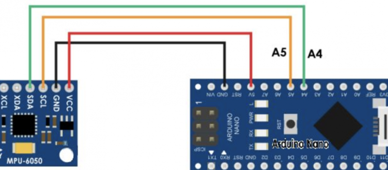
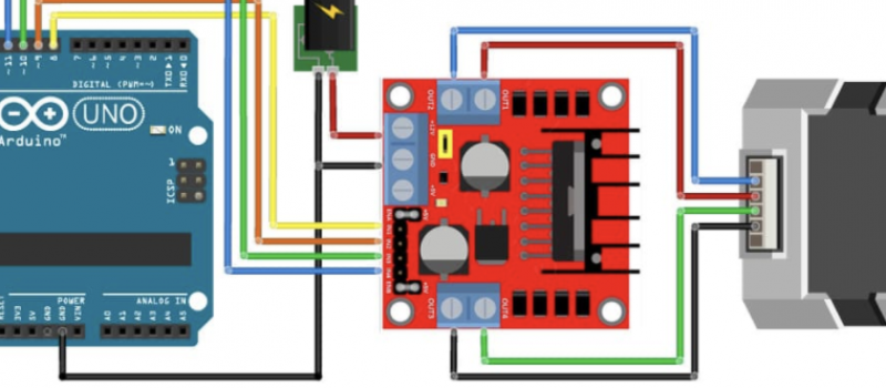
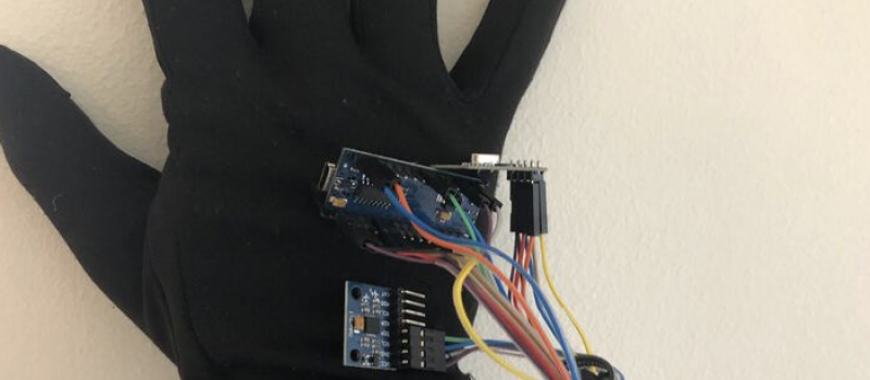
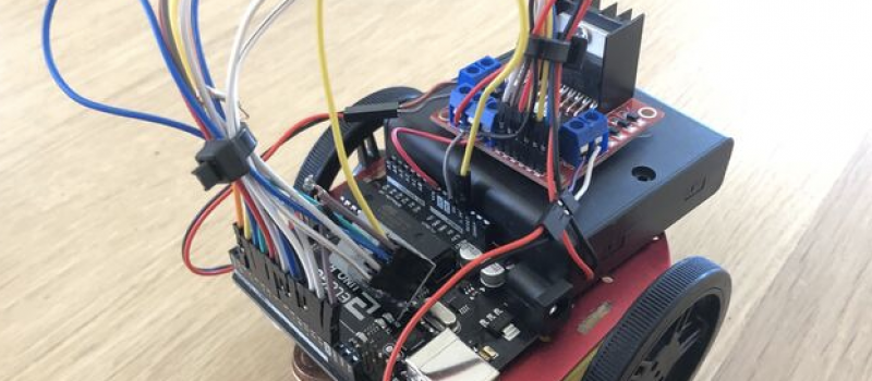
My second milestone was completing the car and glove. This consisted of NRF modules, a motor driver, and an accelerometer. The motor driver allows you to control the individual speed and direction of two individual motors. I connected my motor driver to a battery pack, two motors, and an Arduino Uno. The code I sent receives integers based on the accelerometer data, which the data is then converted into 5 actions, turn left, right, go straight, go backward, and stop. The motor driver uses a 12-volt input, which means you need to connect the +5 voltage output with the VIN spot on the Arduino. This allows the Arduino to convert a voltage of over 5 to 5. The second thing I had to do for my second milestone was completing my accelerometers. The accelerometer is extremely prone to drift when using the gyroscope function, so I had to more heavily rely on the acceleration function. The accelerometer is able to sense the acceleration and or vibration of something moving to deter its x, y, and z axes having 0, 0, 0 be where it was when it was turned on.
First Milestone
-
/* -
* Arduino Wireless Communication Tutorial -
* Example 1 - Transmitter Code -
* -
* by Dejan Nedelkovski, www.HowToMechatronics.com -
* -
* Library: TMRh20/RF24, https://github.com/tmrh20/RF24/ -
*/ -
include <SPI.h> -
include <nRF24L01.h> -
include <RF24.h> -
RF24 radio(7, 8); // CE, CSN
-
const byte address[6] = "00001";
-
void setup() {
-
radio.begin();
-
radio.openWritingPipe(address);
-
radio.setPALevel(RF24_PA_MIN);
-
radio.stopListening();
-
} -
void loop() {
-
const char text[] = "Hello World";
-
radio.write(&text, sizeof(text));
-
delay(1000);
-
}
-
/* -
* Arduino Wireless Communication Tutorial -
* Example 1 - Receiver Code -
* -
* by Dejan Nedelkovski, www.HowToMechatronics.com -
* -
* Library: TMRh20/RF24, https://github.com/tmrh20/RF24/ -
*/ -
include <SPI.h> -
include <nRF24L01.h> -
include <RF24.h> -
RF24 radio(7, 8); // CE, CSN
-
const byte address[6] = "00001";
-
void setup() {
-
Serial.begin(9600);
-
radio.begin();
-
radio.openReadingPipe(0, address);
-
radio.setPALevel(RF24_PA_MIN);
-
radio.startListening();
-
} -
void loop() {
-
if (radio.available()) {
-
char text[32] = "";
-
radio.read(&text, sizeof(text));
-
Serial.println(text);
-
} -
}
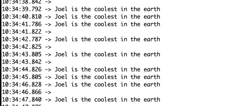
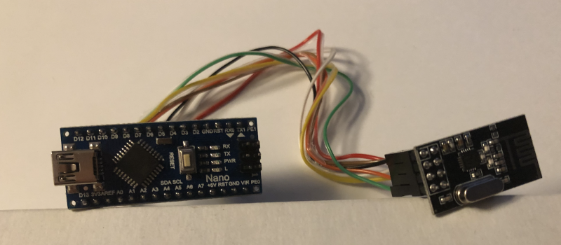
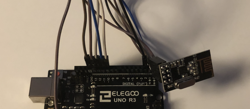
For my first milestone, I completed my NRF modules. NRF modules is a small radio transceiver. It allows you to send information from one NRF to another with and SPI interface (serial peripheral interface). I Completed my NRFs by connecting one NRF module to an Arduino Uno and another to an Arduino Nano. I input a code that causes the NRF module connected to the Arduino Mini to send signals to the other. Then the NRF module on the receiving end will send signals to the Arduino Uno which will then do an action based on what was sent.
https://create.arduino.cc/projecthub/muhammad-aqib/nrf24l01-interfacing-with-arduino-wireless-communication-0c13d4
https://lastminuteengineers.com/l298n-dc-stepper-driver-arduino-tutorial/
https://www.adafruit.com/product/3216https://create.arduino.cc/projecthub/shubhamsuresh/how-to-make-a-gesture-control-robot-at-home-a3f4a4
https://howtomechatronics.com/tutorials/arduino/arduino-wireless-communication-nrf24l01-tutorial/
https://learn.adafruit.com/mpu6050-6-dof-accelerometer-and-gyro/arduino
https://www.instructables.com/id/Accelerometer-MPU-6050-Communication-With-AVR-MCU/


