About Me
Hey! My name is Jessica and I am a Sophomore at Purdue University pursuing a B.S. in Mechanical Engineering. I have always been fascinated by how mechanical objects work and how your imagination can inspire you to create anything. I first became interested in engineering when I realized that I greatly enjoyed math, science, and collaborating with other students like myself! During my exciting experience at BlueStamp Engineering, I created an LED Cube 4x4x4, which incorporated tools and equipment similar to those used in the real world of engineering. My project involved the complete design cycle, with all the challenges, pitfalls, and rewards. I found failure to be a learning lesson, not an end destination. I was passionate about my project and became excited to understand the daily tasks an engineer faces. The insight I gained from this experience instilled in me a love for Mechanical Engineering. Below is the first project I created as an engineering student, I hope you enjoy!
Overview
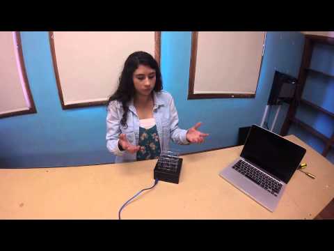
For my main project I was determined to maximize my time in BlueStamp Engineering, so I decided to take on the 4x4x4 LED Cube! My inspiration for creating the cube came from my love for Christmas lights, and it was this inspiration that drove me to finish in the two weeks I had. The instructors and students in BlueStamp Engineering supported and encouraged me to persevere till the end! My goal was to obviously get the LEDs to light up, but to also express my creative side through coding! Since I was able to finish my project with three days remaining, I decided to incorporate a sound sensor to control when the LED light display would run, and for how long. I am grateful for this wonderful opportunity and I thank all of those talented people around me for increasing my love for the engineering field! Enjoy my video!
Wiring Diagram
Bottom Layer Wiring to Cathode Columns

Milestone #2
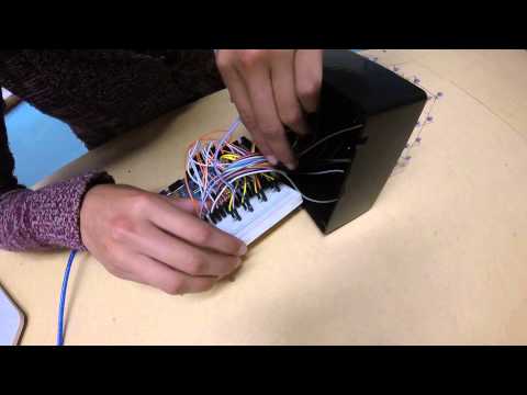
For my second milestone, I successfully completed wiring my LED Cube to the Arduino MEGA and breadboard. Since there were not enough pins on the Leonardo, to allow me to attach all of the wires, I switched to an Arduino MEGA! Before I could begin wiring, I had to understand how the breadboard’s functions. Each of the rows on the breadboard is connected horizontally, not vertically. But the power and ground are connected vertically. The positive sign represents power and the negative represents ground. Once I knew that I was ready to begin wiring! On the LED Cube, all of the columns are negative and the layers are positive, so the voltage travels up to the layers and then comes out through the columns. Since the voltage is traveling to four layers, there are four wires that are attached to Analog Pins A0-A3 and then end at the breadboard where 180 Ohm resistors wait to lower the current. Then after the resistors, there are four other wires that lead to the four pieces of galvanized wire that are attached to the positive layers. For the 16 negative columns, I wired them to the breadboard and then to 16 digital pins on the Arduino. Since I built the cube matrix with 4 positive layers and 16 negative columns, the only way to turn off an LED would be by setting both the layers and columns as OUTPUTS and setting everything HIGH in the Arduino coding. Then to turn them On I would just set one of them on LOW and the other HIGH. My goal for my final project is to understand how to code on the Arduino program and code my own display for the LED Cube.
Milestone #1
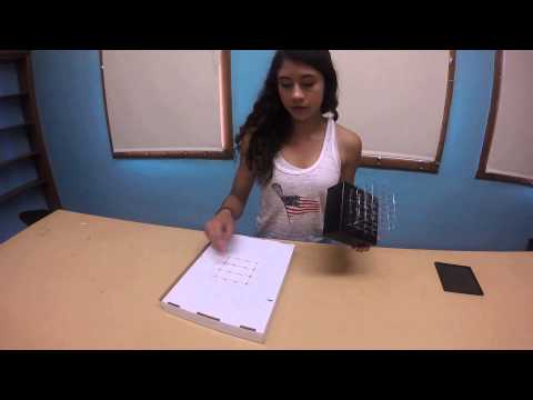
For my first milestone I completed my LED Cube structure and drilled the holes in my project box. To build the LED Cube, I taped a template that I had to the back of my starter project box. Then I punched holes through the box so that I could set the LEDs in the holes. After I had done that, I bent the leads on the LEDs so that they would not touch each other when I start soldering. Once the first 16 LEDs have been placed snug in their own holes and the leads on them have been bent, they were ready for soldering. Firstly, I soldered all of the positive leads, anodes, together and made sure that they did not touch the negative leads, cathodes. Then I repeated this process three more times to end up with a total of four levels.
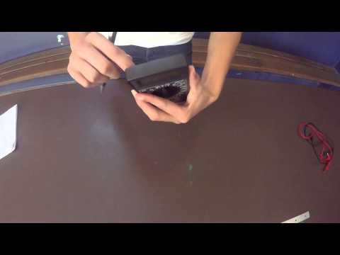
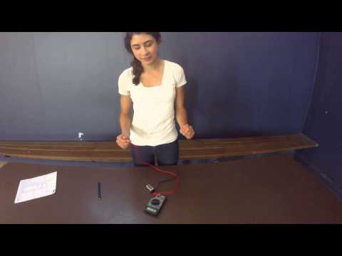
Starter Project – Digital Multimeter
For my starter project I built a digital multimeter. The multimeter is a device that measures voltage, current, and resistance. The multimeter is made up of a PC board with resistors, capacitors, semiconductors, and other important miscellaneous items. To start off, the resistors soldered to the PC board restrict current flow through the circuit so that the current does not burn any other components inside the multimeter. In addition, to the resistors, there are capacitors which are two-terminal electrical components used to stop energy. They also block the flow of direct current while enabling the flow of indirect current. Then there are semiconductors such as diodes, which control direction of current flow, and transistors, which are used to amplify and switch electronic signals and electrical power.