Hi, my name is Jason. I’m a senior at Cherry Creek High School. My starter project was a laser target kit. I started out with it because there was an option to mount a laser to my main project and having a target already built was advantageous. It was fairly easy and I finished it quite quickly with only one mistake. My main project is a simple remote control tank that gets its commands from a PS2 controller. It’s an interesting project because while I have experience building robots and coding I have no experience with robots and have almost never worked on a project of this size alone.
Final Video:
Documentation:
This is a wiring schematic of the tank:

Here is an excel file of my BOM:
And here is a zip file containing source code:
Final Project Milestone 3: Automatic Braking
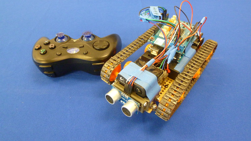
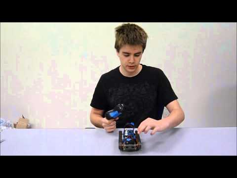
There have been a few changes to the robot during the incorporation of the PING sensor for automatic braking. The most notable, besides the PING itself, are the extra two AA batteries on the back which supply the necessary extra power required to run everything at once. Other than that the components have been rearranged and labeled to be more ergonomic. The PING sensor has been placed on the front of the gearbox and works by emitting a chirp that can’t be heard by the human ear out of one of the eye-like cylinders. The chirp goes out and when it hits an object bounces off of that object and travels back towards the other eye-like cylinder. When the chirp returns the PING registers it and records the length of time the chirp took to return. Based on the known speed of sound it is easy to calculate the distance from the sensor of the object that the chirp hit. It is then a matter of coding in a statement that says if an object is too close to the robot stop using the commands from the PS2 controller and reverse the direction of the motors to stop the tank as quickly as possible as to avoid hitting whatever it is that is in front of the robot. Once the robot has executed its avoidance maneuver and determined that it is safe again the code once again utilizes the commands being given by the PS2 controller. There is also a juggernaut mode that is toggled when the green triangle button is pressed. During this mode the Arduino stops using the PING sensor and engages a permanent safe mode so the tank can be driven over or into whatever is in front of it.
Final Project Milestone 2: Remote Control
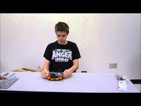
The tank is almost exactly the same as last time. The difference is that now the tank is receiving commands from the PS2 controller through the wireless dongle attached to the Arduino. When a button on the PS2 controller is pressed the controller sends a signal to the dongle which is in turn relayed to the motor shield which uses the code it has to interpret the signal and function accordingly. The code has been changed so that it recognizes when a button is pressed and what button was pressed. The code and motor shield have been set so the trigger buttons L1, L2, R1, and R2 operate the motors. The L buttons operate the left motor and the R buttons the right. The 1 buttons make the motors spin forwards and the 2 buttons backwards. The motors can be operated independently for shallow turns or at the same time in the same direction for straight line movement or in opposite directions for tight turns.
Final Project Milestone 1: Motor test
At this point the robot is set up with a simple plastic chassis with tank treads. It’s powered by two electric DC motors set up on a 38.2:1 gear ratio going to a spiked wheel that moves the tracks. This means that for every 38.2 revolutions a motor does the wheel goes through 1 revolution. Commands for the motors are processed by an Arduino UNO with a motor shield. Power for the Arduino and the motors is supplied from 4 external AA batteries. At the moment the code is simple. The code was written from scratch with the sole purpose of testing the motors and the abilities of the chassis.It runs in a loop to move the robot forwards then move it backwards and spin it in both directions. At this moment the robot is receiving no commands and is just running through a simple loop.
Starter Project:
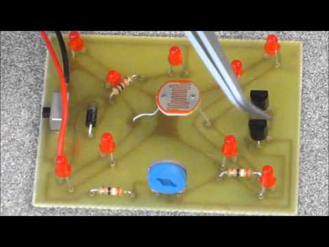
For my starter project I built a laser target kit. It uses a standard 9V battery which has its current lowered by 3 resistors as to not burn out the LED bulbs. After the resistors the power Runs to a CDS photo-resistor.
The CDS photo-resistor is a light controlled variable resistor. The CDS works by using a material that has a high resistance in the darkness but a low resistance in light because the semiconductor takes energy from the light that hits it to excite its electrons and increase its electrical conductivity and decrease the resistance of the semiconductor. The CDS draws the current away from the two transistors.
The two transistors act as a switch by use of the loss of input voltage from the CDS allow current to flow to a series of 8 LEDs set up in an “x” pattern with the CDS in the center lighting them up.
Before the CDS there is also a potentiometer before the CDS which allows the sensitivity of the CDS to be changed so the target can work in environments ranging from lit rooms to pitch black. The potentiometer works by being an adjustable resistor so as the resistance changes the corresponding current changes as well.
Also to aid its use in darker environments there is a ninth LED bulb hooked up to the battery, that can only be lit when the switch is in a certain position thanks to a diode, which uses two different types of semiconductors to create a neutral charged boundary region through which electrons can only flow in one direction only allowing the current to pass when it’s going in a certain direction. This ninth LED is placed just below the CDS and acts as a target finder so one can get an idea of where the CDS is in low visibility environments.