RC Tank
This is an Rc tank controlled by a PS2 controller connected to an Arduino, as well as a laser pointer turret. I made an outer hull out of plastiacard to make it look more like a tank.
Engineer
Jake C
Area of Interest
Explosives Engineering/ Mechanical Engineering/ Electrical Engineering/ Finance
School
SAR High School
Grade
Incoming Junior
Finial Milestone
For my final milestone, I have completed a large portion of my modifications. The 2 main ones are a work in progress outer hull and turret with a laser. The outer hull is made out of plasticard or styrene. Its main purpose is to keep all the internal wires from going all over the place as well as holding the servos in place. The turret is comprised of 2 servos and a laser diode. The 2 servos allow for horizontal and vertical traverse emulating the action of a tank turret. There are 2 main types of DC servo motors, continues and regular a continuous servo can turn 360 while a regular servo can only turn 180. Servos are controlled by PWM protocol, PWM is when an electrical signal is chopped into many smaller “packets” thus imitating an analog signal this allows you to achieve more finite control over a motor rather than a binary on and off. A laser diode is, in essence, a semiconductor that emits light instead of heat the semiconductor has 2 parts P and N. The N part is composed of gallium arsenide coated with a reflecting material, the P part is composed of gallium arsenide and selenium coated with a reflecting material. The N part has holes in it in order to promote gaining an electron. While selenium on the P part promotes losing an electron. Because of this the excess electrons and the “holes” are attracted to each other and form a photon. Because of the reflective coating, the photons coalesce a specific frequency, polarisation, and phrase. Essentially identical photons which create a coherent color and, power output, but we are missing the third most important part of a laser coherency. in order to achieve this, a lens is used to condense the beam, thus a Lazer is emitted for the diode.
Reflection
while at Bluestamp I learned many things the most impactful skill that I learned was how to approach and solve a problem with many variables. for example when my tank bricked and I had no idea on how to fix it, what I had to do was take it apart and slowly add back on items. this helped me reduce the number of variables I had to deal with.
Second Milestone
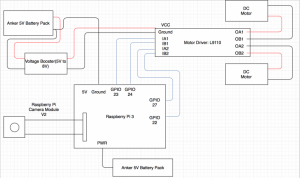
For my second milestone, I had to finish the main project, this meant I had to get the 3 main electronic components of the tank done. They were: the Ps2 receiver, the motor driver, and the Arduino.
The Ps2 receiver is what allows me to use the Ps2 controller to connect the Arduino and thus the motor driver. The Ps2 controller has 9 total pins but only 6 are needed, the pins are, in no particular order, clock, data, command, power, ground, and attention. Clock and data send information from the master device to the slave, in this case, the master device is the Ps2 controller and the slave is the Ps2 receiver and by extension the Arduino. Command is what the Ps2 receiver uses to communicate with the master device. Power and ground are connected in the usual manner. Finally, attention is what the master uses to tell the slave that it is active.
The motor driver is, in essence, an H bridge. An H bridge allows current to be sent in the opposite direction or flip the polarity. This allows you to reverse the direction of a DC motor, this allows me to turn the tank.
The Arduino is the “brains” of the tank, the 2 main functions I used the Arduino for where debugging with the serial monitor and analyzing inputs from the Ps2 receiver then sending those outputs to the H bridge. Serial is a communication protocol used by to Arduino to transmit data one bit at a time one way. This allows for debugging using the “serial monitor”, the monitor allows you to view print statements in your code from the Arduino allowing you to debug your code. Secondly to receive inputs from the Ps2 controller I had to connect the Ps2 receiver to a few digital pins as well as ground and 3.3 volts. Pins on an Arduino are used to output 5 volts at 40 Ma, this allows you to choose when to power something or to receive an input. The other type of pin on an Arduino is an analog pin. Analog pins can send and receive analog inputs and outputs. The way the Arduino (a digital device) can send an analog signal is by Pulse Width Modulation or PWM, PWM is when an electrical signal is chopped into many smaller “packets” this is a very good imitation of an analog signal as well controlling motors as motors have inertia, therefore, won’t react as quickly to sudden current changes.
Although for my tank I decided to use an H bridge which is hooked up to the digital pins. Once an output is sent from the Ps2 controller to the Arduino the Arduino analyzes it and then activates the corresponding digital pins which activate a certain orientation of an H bridge which then sends power to the motors thus allowing the tank to move.
the bolded section of the code is the aspect that interacts with the motors and ps2 receiver


#include <L298N.h>
#define ENa 10
#define IN1 9
#define IN2 8
#define ENB 5
#define IN3 7
#define IN4 6
L298N motor1(ENa, IN1, IN2);
L298N motor2(ENB, IN3, IN4);

#include <PS2X_lib.h>  //for v1.6

PS2X ps2x; // create PS2 Controller Class

//right now, the library does NOT support hot pluggable controllers, meaning
//you must always either restart your Arduino after you conect the controller,
//or call config_gamepad(pins) again after connecting the controller.
int error = 0;
byte type = 0;
byte vibrate = 0;

void setup() {
Serial.begin(57600);
motor1.setSpeed(255); // an integer between 0 and 255
motor2.setSpeed(255); // an integer between 0 and 25
//CHANGES for v1.6 HERE!!! **************PAY ATTENTION*************

  error = ps2x.config_gamepad(13, 11, 4, 12, true, true); //setup pins and settings:  GamePad(clock, command, attention, data, Pressures?, Rumble?) check for error

  if (error == 0) {
Serial.println("Found Controller, configured successful");
Serial.println("Try out all the buttons, X will vibrate the controller, faster as you press harder;");
Serial.println("holding L1 or R1 will print out the analog stick values.");
Serial.println("Go to www.billporter.info for updates and to report bugs.");
}

  else if (error == 1)
Serial.println("No controller found, check wiring, see readme.txt to enable debug. visit www.billporter.info for troubleshooting tips");

  else if (error == 2)
Serial.println("Controller found but not accepting commands. see readme.txt to enable debug. Visit www.billporter.info for troubleshooting tips");

  else if (error == 3)
Serial.println("Controller refusing to enter Pressures mode, may not support it. ");

  //Serial.print(ps2x.Analog(1), HEX);

  type = ps2x.readType();
switch (type) {
case 0:
Serial.println("Unknown Controller type");
break;
case 1:
Serial.println("DualShock Controller Found");
break;
case 2:
Serial.println("GuitarHero Controller Found");
break;
}

}

void loop() {

  /* You must Read Gamepad to get new values
Read GamePad and set vibration values
ps2x.read_gamepad(small motor on/off, larger motor strenght from 0-255)
if you don't enable the rumble, use ps2x.read_gamepad(); with no values

    you should call this at least once a second
*/


  if (error == 1) //skip loop if no controller found
return;

  if (type == 2) { //Guitar Hero Controller

    ps2x.read_gamepad();          //read controller

    //  if (ps2x.ButtonPressed(GREEN_FRET))
Serial.println("Green Fret Pressed");
if (ps2x.ButtonPressed(RED_FRET))
Serial.println("Red Fret Pressed");
if (ps2x.ButtonPressed(YELLOW_FRET))
Serial.println("Yellow Fret Pressed");
if (ps2x.ButtonPressed(BLUE_FRET))
Serial.println("Blue Fret Pressed");
if (ps2x.ButtonPressed(ORANGE_FRET))
Serial.println("Orange Fret Pressed");

if (ps2x.ButtonPressed(STAR_POWER))
Serial.println("Star Power Command");

    if (ps2x.Button(UP_STRUM))         //will be TRUE as long as button is pressed
Serial.println("Up Strum");
if (ps2x.Button(DOWN_STRUM))
Serial.println("DOWN Strum");

if (ps2x.Button(PSB_START))                  //will be TRUE as long as button is pressed
Serial.println("Start is being held");
if (ps2x.Button(PSB_SELECT))
Serial.println("Select is being held");

if (ps2x.Button(ORANGE_FRET)) // print stick value IF TRUE
{
Serial.print("Wammy Bar Position:");
Serial.println(ps2x.Analog(WHAMMY_BAR), DEC);
}
}

  else { //DualShock Controller

    ps2x.read_gamepad(false, vibrate);          //read controller and set large motor to spin at 'vibrate' speed

    if (ps2x.Button(PSB_START))                  //will be TRUE as long as button is pressed
Serial.println("Start is being held");
if (ps2x.Button(PSB_SELECT))
Serial.println("Select is being held");

if (ps2x.Button(PSB_PAD_UP)) {        //will be TRUE as long as button is pressed
Serial.print("Up held this hard: ");
Serial.println(ps2x.Analog(PSAB_PAD_UP), DEC);
}
if (ps2x.Button(PSB_PAD_RIGHT)) {
Serial.println("Right held this hard: ");
Serial.println(ps2x.Analog(PSAB_PAD_RIGHT), DEC);
}
if (ps2x.Button(PSB_PAD_LEFT)) {
Serial.println("LEFT held this hard: ");
Serial.println(ps2x.Analog(PSAB_PAD_LEFT), DEC);
}
if (ps2x.Button(PSB_PAD_DOWN)) {
Serial.print("DOWN held this hard: ");
Serial.println(ps2x.Analog(PSAB_PAD_DOWN), DEC);
}

vibrate = ps2x.Analog(PSAB_BLUE);        //this will set the large motor vibrate speed based on
//how hard you press the blue (X) button

    if (ps2x.NewButtonState())               //will be TRUE if any button changes state (on to off, or off to on)
{


      if (ps2x.ButtonPressed(PSB_L2)) {
Serial.println("L2 pressed");
motor2.forward();
Serial.println("motor go");
}
if (ps2x.ButtonPressed(PSB_R2 )) {
Serial.println("R2 pressed");
motor1.forward();
Serial.println("motor go");
}
if (ps2x.ButtonReleased(PSB_R2 )) {
motor1.stop();
Serial.println("motor stop");
}
if (ps2x.ButtonReleased(PSB_L2 )) {
motor2.stop();
Serial.println("motor stop");
}
if (ps2x.ButtonPressed(PSB_L1)) {
motor2.backward();
Serial.println("motor go");
}
if (ps2x.ButtonPressed(PSB_R1)) {
motor1.backward();
Serial.println("motor go");
}
if (ps2x.ButtonReleased(PSB_L1)) {
motor2.stop();
Serial.println("motor stop");
}
if (ps2x.ButtonReleased(PSB_R1)) {
motor1.stop();
Serial.println("motor stop");
}


delay(50);

}
First Milestone
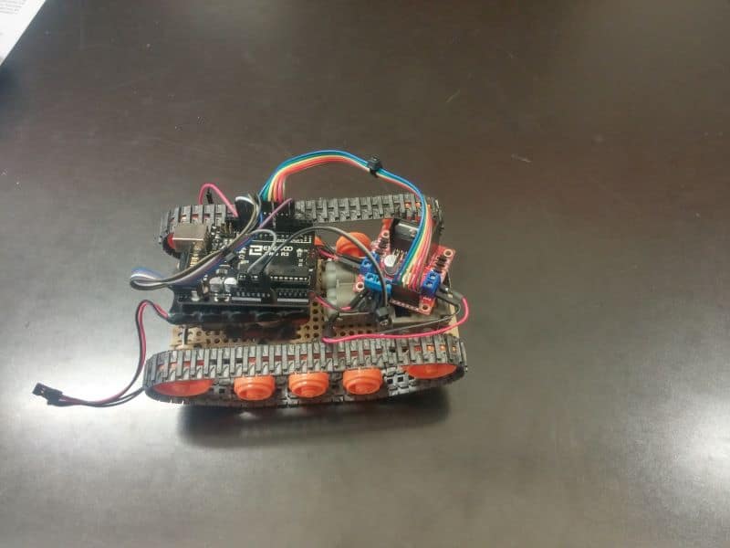
My first milestone was to be able to power the motors by the battery. To do this I had to make 3 main subassemblies, the gearbox, the chassis, and the wheels. The most complex part was the gearbox this was due to many different ways to build it. The variant I chose to build was variant C this gave me rpm 114.7 which gives me 115 rpm and 809-gram force cm. This is fairly in the middle in terms of both torque and rpm this will allow me to add more attachments later as I could still have enough torque to move the tank. The other parts where simple to assemble. Below are images of the tank
rc tank
testing internals
this is the main subassemblies of the tank are the chassis, wheels and the gearbox. the wheels are the orange wheels the chassis is the tan plate that everything is attached to. finally, the gearbox is the grey box with blue and yellow gears inside.
Starter Project
My starter project is the useless machine, a machine that turns itself off when you turn it on. It is composed of 3 main subassemblies: the outer box, the motor and arm, and the PCB. The box is made out of black acrylic and has a flap for the motor am to go out of.
I faced a few challenges while building the starter project, the biggest one I faced was that I soldered the main switch on an angle that would not allow the arm to interface with the switch. To rectify the mistake I had to desolder and then resolder the switch into the correct position.
Below is a schematic of the circuit for the Useless machine.
link to the instructions: http://www.spikenzielabs.com/Downloadables/uselessmachine/Useless-Machine-Soldering-Edition.pdf