Introduction
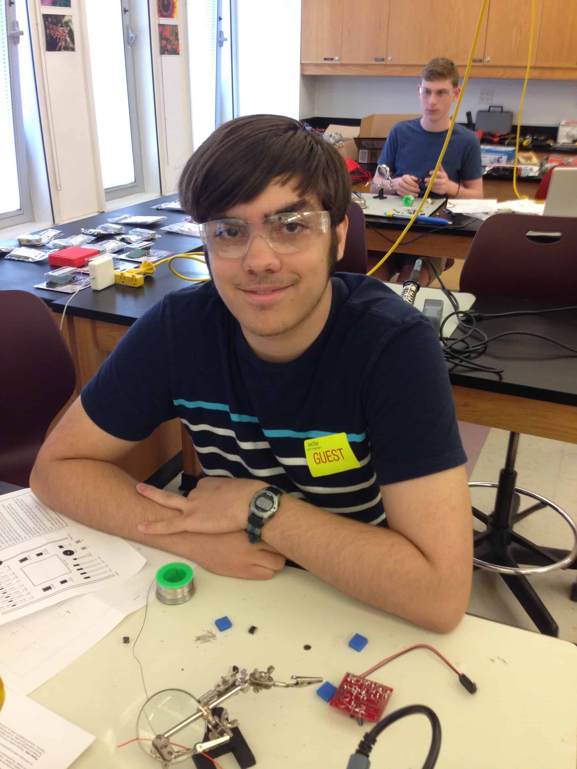
Hello! My name is Jacob, and I will be a senior at Horace Mann next year. I chose the laser harp as my project. I chose this project because I am interested in music as well as engineering. I play the trombone and I used to play the piano, so creating an instrument of my own to play sounded fun.
Main Project – Laser Harp
Final Milestone
The code works properly but requires the Tone library, which itself requires other libraries. The libraries needed are the following: stdint.h, inttypes.h, pins_arduino.h, Arduino.h, interrupt.h, io.h, and pgmspace.h. These libraries should be included with arduino, but were not included with my version. Here is the harp code and tone library, which contains two files: Tone Tone2.
Milestone 1
The laser/photodiode setup consists of a laser pointed directly at a photodiode. The laser emits light that hits the photodiode, which allows current to pass. When the laser is interfered with, its light will not hit the photodiode, which will no longer allow a current to pass through. The change in behavior of the photodiode can be easily detected with the analogRead function of an arduino, and a sound can be outputted to the speaker when the change is detected. In the video, I had one laser/photodiode unit working, but afterwards I added a second one and got them to play independent of each other and simultaneously. I am using an arduino microcontroller with arduino’s programming language, which contains a built in tone function. However, the tone function doesn’t allow 2 notes to be played at the same time, even in different pins. I used this library, which allowed two different tones to be played into different pins at the same time. I wired 2 pins into the same input in the speaker, so the two different tones could be played through the same speaker. This should work with 8 pins in the final project, but the sound quality of a chord using this method is not ideal.
I have also designed the harp in autoCAD, a 3D modelling software. I started designing my harp not knowing how to use autoCAD at all, but I eventually learned enough to create this design for my harp. The model has 16 holes, 8 for the photodiodes and 8 for the laser diodes. The holes continue around the harp so that wires can be placed through the harp to the arduino microcontroller. This model doesn’t include the case for the arduino, which will be on the bottom, because I created that part after the harp was split into printable parts.

I did the junior theremin as my starter project. The actual construction of the theremin mostly involved soldering the components onto the breadboard. The one issue that I had was that I put the chips in their slots upside-down because I used the writing as a reference for orientation and not the bumps that specifically mark orientation.
The wire that is used to create the sound uses the principle of capacitive sensing to adjust the frequency of the sound. A standard capacitor has two plates that, when a power source is supplied, will create a potential difference. To create the potential difference, the circuit must induce a current to the capacitor. This can be exploited because the hand can act as the grounded plate of a capacitor and induce a charge in whatever is acting as the power supply, in this case the wire. This current will continue to flow through the wire into the 555 chip. This chip is an oscillator which creates a pulse based on the current flowing into it, so the chip will create a pulse of a frequency relative to the amount of current in the wire. The amount of current in the wire increases when the capacitance increases, and capacitance increases as the distance between the plates decreases. Therefore, the current flowing to the 555 chip will increase as the hand moves closer to the wire, causing the pitch to increase.
A 555 chip converts the interaction with the wire into a pulse, and a PIC chip uses button inputs to modulate the pulse and control LED’s. The PIC chip sends the final pulse to the PIEZO buzzer that creates sound from the pulse.


