
Color Tracking Robot
There are 3 components to the Color Tracking Robot: The sensor, the motors, and the camera. The entire robot is powered by the Raspberry Pi 3. The robot should be able to detect the color red with the camera, and depending on its position drive towards that red object. While the sensor prevents it from crashing with whatever it may be tracking.
Engineer
Jacob G
Area of Interest
Software/Mechanical Engineering
School
George Washington High School
Grade
Incoming Senior

Project Progress
Reflection
At BlueStamp I definitely learned a lot and had a lot of fun. The experience was extremely useful, and I don’t think I would have gotten the same exposure anywhere else.
My favorite part would have to be the coding aspect. I have always had an interest in software and coding, and I really got to test my skills with this project. I had to learn a new language which is always very fun, and seeing all my code come together and work is always very rewarding.
I want to keep working on my project, I was thinking of adding servos, or facial recognition, or set up a VNC. I would also like to try making my own project some time in the future.
Overall I really enjoyed my experience, and I am very proud of what I made
Final Milestone
For my third and final milestone, my robot is no longer connected to my laptop. I achieved this by editing the rc.local files on my Raspberry Pi, and creating a script that would run my code as soon as their was any power in my Raspberrhy Pi. The biggest problem with that would have to be that the only way to stop my robot is to disconnect the power source. I would like to set up a VNC, but the internet we are using does not allow for SSH.

Second Milestone
For my second milestone I have assembled my main three components, and gotten them to all work together onto the chassis. I had a lot of problems with the Raspberry Pi, I ended up burning and disabling internet connectivity on a previous Raspberry Pi, but currently this one works. For the next milestone I would like to get it working without the ether net cable connected to the robot.
Project Demo
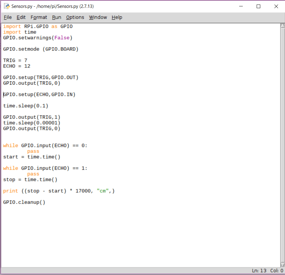
My robot works by using the camera in the front to run live video to the Raspberry Pi, and using a library called OpenCV, I created what was is called a mask, to set a range of color which the robot highlights in the frame. Then wherever the largest red object is in the frame, the robot will move in an attempt to center it. I have a L298N bridge which allows me to control the motors, as well as being more convenient than having to wire to motors individually. Lastly, I have a HC-SRO4 ultra sonic sensor, which measures the distance between my robot and the closest object in front of it by releasing a sound wave and measuring the time it takes for the sound wave to bounce back. Then in my code, I use the speed of sound in an equation to find the distance.
First Milestone
For my first milestone I got my motors, camera, and sensors working. Currently they all run independently, but for my next step I would like to bring them all together on a chassis. The most difficult part of this project so far would have to be connecting my raspberry pi to my laptop using SSH. SSH, or Secure Shell, allows two computers to connect securely over an unsecured network. I also had some problems with the camera, but they were solved fairly quickly

The first component I built for my project was the sensor. The sensors read the distance from the closest thing in relation to the sensor, in centimeters. I plan to use my sensors in order to prevent my robot from crashing into whatever object it is following
For my motors I connected them to a L298N motor driver which allows me to run both motors together. It is also connected to battery and converter so it can run semi-independently from my raspberry pi.

Lastly I got the camera to work. For the camera I had to install openCV, which are a set of libraries which are used for real time computer vision. Downloading the library was very difficult, it was not very intuitive, luckily Kevin provided me with a guide to download the the libraries through the control panel in the raspberry pi. Currently I am able to upload live camera footage from the camera to my laptop.

Here is a link to the Color Tracking Robot modules
I think my project is going over pretty well. I’ve gotten a a sizable amount of work done, but I did run into a few set backs, primarily being connecting to my Raspberry Pi through SSH. I believe that there is still one more very difficult challenge being the color recognition. I hope once I get the computer vision done, I can finish the entire project soon after.
For my next milestone, I would like to get the color tracking to work, and have all my components working together all on the robot.
Starter Project
My Starter Project is the Minty Booster, which is pretty much a portable charger. It takes batteries, and you could connect it to a USB, and from there charge anything. I think the process of making the project went over smoothly. The biggest problem for myself would have to be soldering, as it was completely new to me. Additionally, there was a lot of soldering needed on the small circuit in order to complete the project. Overall I enjoyed making this project and I am happy with the outcome.
Demonstration
How it works
How the Minty Boost works is that it takes in 3 V from batteries, and it uses a converter, an inductor, a diode, and two capacitors, in order to increase the voltage to 5 V which is enough to charge a phone. The voltage from the batteries flows into the inductor, where it is stored as energy in the inductor’s magnetic field, generated by the current. When the energy is stored in the inductor, more voltage is created. The converter is able to detect the amount of energy inside the inductor and flip a switch on and off. If the switch is off, the energy will flow back into the inductor. If it is open it will flow through the diode. Once it detects a significant amount of energy, it will flip on a switch, which will force the energy to flow through the diode. Then the now 5 V of energy flows to the capacitors where it is stored for use. Additionally, the circuit and battery case are conveniently encased inside a tin box case.
Minty Boost Schematic
