Reflection
Looking back at my three weeks, it seems like a brief period, but there were some very long and slow passing nine hour days of troubleshooting. I came into this program not knowing much about engineering except for the fact the engineers built things and make them better. Now I know that engineers are all that and more. They are visionaries for the future constantly looking to make the world around them better. Along with learning the mind set of an engineer, I picked up some skills such as basic coding and how to wire a circuit along with knowing to troubleshoot for both of that f a problem comes across. My first week here I felt baffled and learning which each of the parts of the Minty Booster seemed impossible and a miserable task but, I now would not trade anything for the experience and skills I learned here. This program gave me more confidence to think about pursuing a career in bioengineering. I am very excited to take the skills I learned here and foster it to create something great to benefit the world.
Final Milestone
For my final milestone, I coded the glove and robotic hand to play rock paper scissors against each other. I started with my robotic hand: I coded it to pick a random motion of “rock,” “paper,” or “scissors.” Coding this command is not as simple as it sounds though, I had to figure out the position of each finger and code it so that the servos would rotate the right direction and the right amount to create each of these motions. Once I had that completed, I moved on to the glove. The flex sensors can monitor which fingers on a hand are up or not. Since the flex sensors read each finger I was able to code it to recognize the position of a human hand when it is in “rock,” “paper,” or “scissors.” Ex. “paper” would be all fingers up so each finger would read a high number showing it was flexed.
Once I was done with both of these components, I combined the code so that the robot could know if it had won or lost the round. Once I completed this to check if it worked, I added in a LED screen to display the score. I was able to hook up the LCD screen to the Arduino but they shared some needed pins, and so I changed the layout a little so that they could share these pins by putting them in the same column on a breadboard. Once I got the screen to work I then some more modifications such as starting position for the main hand and the word shoot showing up on the screen when the computer side was ready to get a human’s choice of rock, paper or scissor. Once I finished the code I got the game to pick up the correct score nearly 90% of the time. Unfortunately, when I decided to move to a proto board the wiring got messed up and I am currently working to get it back to its former state.
Second Milestone
For my second milestone, I rewired my hand with fishing wire. Doing this appeared to give a hand more mobility and allowed it to react to commands faster. I also added the additional servo to the front to make the thumb work independently. To make this happen, I programmed the fifth servo and flex sensor and added these to the code. Once the plastic bolts and screws came, I replaced most of the metal ones with the plastic. The reason why I put in the plastic bolts is it had more fluid motions with them and the project looked more consistent as a whole.
First Milestone
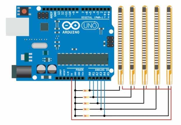
My first step in creating the Robotic Hand was to work with the flex sensors. For this project, I used flex sensors because they respond to bending which is perfect to mimic human finger motions.The Flex sensors work by measuring the resistance of the strip when bent. There is an ink-like substance on the bottom of the strip that acts like a rubber band and when it is bent the ink moves. This movement’s able to be turned into a calculation of resistance and ultimately data that the motor can use to move. I connected the flex sensors to the Arduino board and made sewed the flex sensors onto a glove. The Arduino is like the brain of the operation and code that is made can be uploaded here.
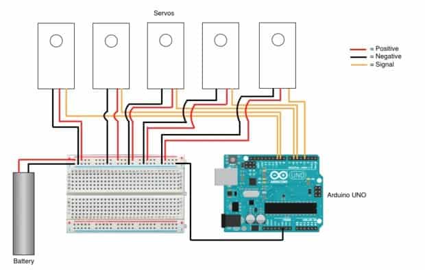
The motors were my next target. Before connecting the motors to the board, I tested each of them individually by hooking them up to the Arduino and running a test code. I then proceeded to connect the motors to the Arduino and upload the code. When I tried testing it, none of the motors moved. The motors were unresponsive which confused me because all the sensors and motors were working and the wiring between them was correct. Troubleshooted it and recognized the problem had to do with the power source. I accidentally connected the battery to the Arduino when I was supposed to connect it to the breadboard, this didn’t work because there was not enough power going through the circuit to power all the servos. My final motor code
Next, I assembled the 3D printed hand. I could not find any thinner wire than a copper wire, so I strung each finger with wire so that they could be pulled up in down by the motors. I strung one wire in the front and one wire down the back of each finger. I then realized that my fifth flex sensor was not operating properly and I would have to replace it, so my robotic hand does not have a functioning thumb yet.
Servo Motor Schematic

Flex sensor schematic

Starter Project
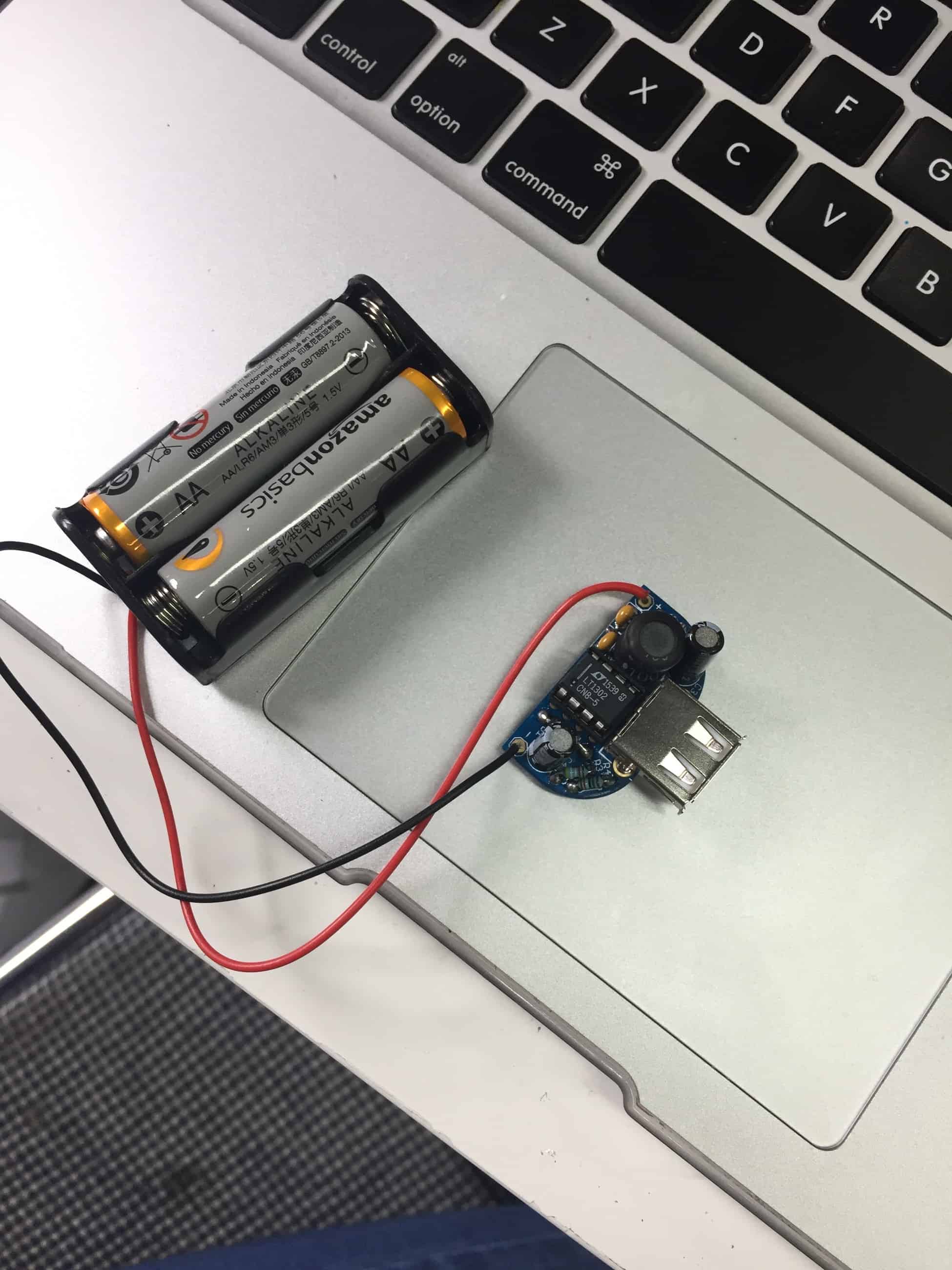
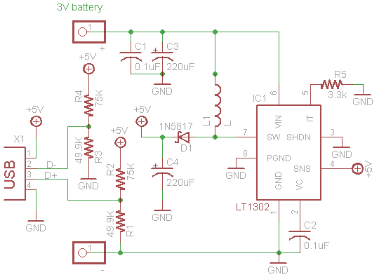
For my starter project, I created the Minty Boost which is a portable charger. In this charger, I used two AA batteries which had a combined voltage of three volts. To charge a device, the circuit had to put out a 5V. To make this happen, the boost converter converts the voltage to five volts. The inductor and capacitors on the circuit helped store the energy and allowed enough to be built up so that enough energy would be in the circuit at any given time. A Inductor, also called a coil or reactor: is a passive two-terminal electrical component that stores electrical energy in a magnetic field when electric current is flowing through it. The capacitor is employed to conduct an alternating current around a component or group of components. The resistors helped regulate the voltage so that the circuit would not overheat. The final part was the rectifier which contributed to making sure the energy was flowing the right way and charged the device. The USB port allows the device to have access to this power.
Minty Booster

Minty Boost Layout


