#include <SPI.h> //SPI library for communicate with the nRF24L01+
#include "RF24.h" //The main library of the nRF24L01+
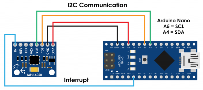
#include "Wire.h" //For communicate
#include "I2Cdev.h" //For communicate with MPU6050
#include "MPU6050.h" //The main library of the MPU6050
//Define the object to access and cotrol the Gyro and Accelerometer (We don't use the Gyro data)
MPU6050 mpu;
int16_t ax, ay, az;
int16_t gx, gy, gz;
//Define packet for the direction (X axis and Y axis)
int data[2];
//Define object from RF24 library - 9 and 10 are a digital pin numbers to which signals CE and CSN are connected.
RF24 radio(9,10);
//Create a pipe addresses for the communicate
const uint64_t pipe = 0xE8E8F0F0E1LL;
void setup(void){
Serial.begin(9600);
Wire.begin();
mpu.initialize(); //Initialize the MPU object
radio.begin(); //Start the nRF24 communicate
radio.openWritingPipe(pipe); //Sets the address of the receiver to which the program will send data.
}
void loop(void){
//With this function, the acceleration and gyro values of the axes are taken.
//If you want to control the car axis differently, you can change the axis name in the map command.
mpu.getMotion6(&ax, &ay, &az, &gx, &gy, &gz);
//In two-way control, the X axis (data [0]) of the MPU6050 allows the robot to move forward and backward.
//Y axis (data [0]) allows the robot to right and left turn.
data[0] = map(ax, -17000, 17000, 300, 400 ); //Send X axis data
data[1] = map(ay, -17000, 17000, 100, 200); //Send Y axis data
radio.write(data, sizeof(data));
}
#include <SPI.h> //SPI library for communicate with the nRF24L01+
#include "RF24.h" //The main library of the nRF24L01+
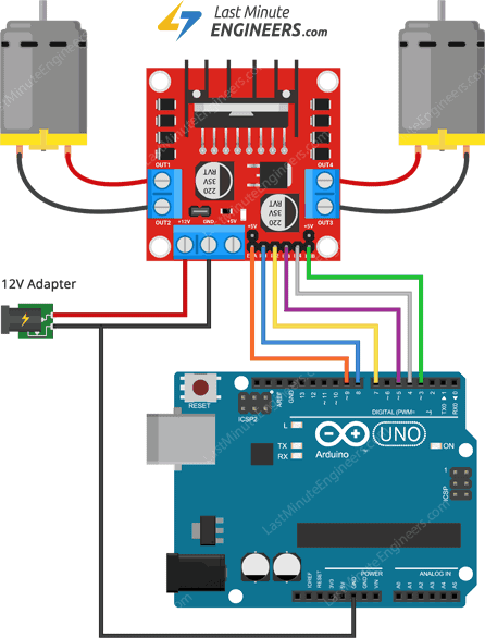
//Define enable pins of the Motors
const int enbA = 3;
const int enbB = 5;
//Define control pins of the Motors
//If the motors rotate in the opposite direction, you can change the positions of the following pin numbers
const int IN1 = 2; //Right Motor (-)
const int IN2 = 4; //Right Motor (+)
const int IN3 = 7; //Left Motor (+)
const int IN4 = 6; //Right Motor (-)
//Define variable for the motors speeds
//I have defined a variable for each of the two motors
//This way you can synchronize the rotation speed difference between the two motors
int RightSpd = 130;
int LeftSpd = 150;
//Define packet for the direction (X axis and Y axis)
int data[2];
//Define object from RF24 library - 9 and 10 are a digital pin numbers to which signals CE and CSN are connected
RF24 radio(9,10);
//Create a pipe addresses for the communicate
const uint64_t pipe = 0xE8E8F0F0E1LL;
void setup(){
//Define the motor pins as OUTPUT
pinMode(enbA, OUTPUT);
pinMode(enbB, OUTPUT);
pinMode(IN1, OUTPUT);
pinMode(IN2, OUTPUT);
pinMode(IN3, OUTPUT);
pinMode(IN4, OUTPUT);
Serial.begin(9600);
radio.begin(); //Start the nRF24 communicate
radio.openReadingPipe(1, pipe); //Sets the address of the transmitter to which the program will receive data.
radio.startListening();
}
void loop(){
if (radio.available()){
radio.read(data, sizeof(data));
if(data[0] > 380){
//forward
analogWrite(enbA, RightSpd);
analogWrite(enbB, LeftSpd);
digitalWrite(IN1, HIGH);
digitalWrite(IN2, LOW);
digitalWrite(IN3, HIGH);
digitalWrite(IN4, LOW);
}
if(data[0] < 310){
//backward
analogWrite(enbA, RightSpd);
analogWrite(enbB, LeftSpd);
digitalWrite(IN1, LOW);
digitalWrite(IN2, HIGH);
digitalWrite(IN3, LOW);
digitalWrite(IN4, HIGH);
}
if(data[1] > 180){
//left
analogWrite(enbA, RightSpd);
analogWrite(enbB, LeftSpd);
digitalWrite(IN1, HIGH);
digitalWrite(IN2, LOW);
digitalWrite(IN3, LOW);
digitalWrite(IN4, HIGH);
}
if(data[1] < 110){
//right
analogWrite(enbA, RightSpd);
analogWrite(enbB, LeftSpd);
digitalWrite(IN1, LOW);
digitalWrite(IN2, HIGH);
digitalWrite(IN3, HIGH);
digitalWrite(IN4, LOW);
}
if(data[0] > 330 && data[0] < 360 && data[1] > 130 && data[1] < 160){
//stop car
analogWrite(enbA, 0);
analogWrite(enbB, 0);
}
}
}