Gesture-controlled RC car with Robot Arm
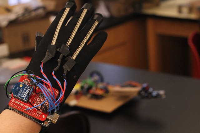
The gesture controlled rc car with robot arm is a two part project. One part is the glove worn to detect gestures to control the car and arm. The second part is the rc car and robot arm which receives commands from the glove to move.
Name
Ilan
Area of Interest
Electrical Engineering
School
Poly Prep Country Day School
Grade
Incoming Sophomore
Reflection
Whenever I am asked what I want to be when I grow up I always reply “an engineer.” When I would say this everyone would always follow up with what kind of engineer I wanted to be. I never had a real answer to this question because I never had the resources to try or even know what some of these sectors of engineering were. Through Bluestamp, however, I now know what these terms mean and can proudly respond that I want to be an electrical engineer.
2x Arduino Uno – https://store.arduino.cc/usa/arduino-uno-rev3 – $22.00
Dual Motor Driver – https://www.elegoo.com – $16.99
Robot Arm Gripper – https://www.sunfounder.com/rollpaw.html – $19.99
2x XBEE Shield – https://www.sparkfun.com/products/12847 – $14.95
2x XBEE Explorer – https://www.sparkfun.com/products/11697 – $24.95
2x XBEE – https://www.amazon.com/XBee – $26.95
Servo – https://hobbyking.com – $6.90
Lithium Ion Battery – https://www.amazon.com – $16.99
2x 12V DC Motor – http://www.dx.com – $6.47
Switch – https://www.sparkfun.com/products/14330 – $1.50
2x Button – https://www.sparkfun.com/products/9190 – $0.50
4x Flex Sensors – https://www.sparkfun.com/products/8606 – $12.95
Portable Charger – https://www.anker.com – $19.99
Wheels – https://www.pololu.com/product/1433 – $9.25
Mounting Hub – https://www.pololu.com/product/1081 – $6.95
Lithium Battery Charger – https://www.amazon.com – $21.75
Final Milestone
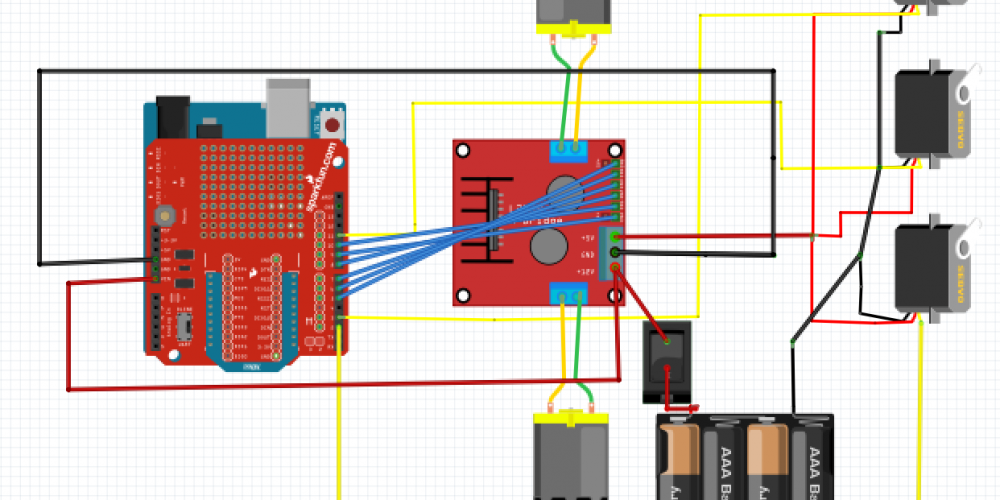
Car, Arm and Gun Schematic

For Glove:
// Router!
int flexSensorPin1 = A0;
int flexSensorPin2 = A1;
int flexSensorPin3 = A2;
int flexSensorPin4 = A3;
int ledPin = 13;
int button = 8;
int button_read = 0;
int fireButton = 7;
int fireButton_read = 0;
int b = 0;
int k = 0;
char s_str1[2];
char s_str2[2];
char s_str3[2];
char s_str4[2];
char command = ‘e’;
String str1, str2, str3, str4;
void setup() {
pinMode(button, INPUT); // The button is going to control if we are going to control either the robot arm or the motors.
pinMode(fireButton, INPUT);
Serial.begin(9600);
}
void loop() {
if (digitalRead(button) == LOW) // check if button was pressed
{
b++;
b = b % 2;
delay(250);
if (b == 0) {
command = ‘s’;
digitalWrite(ledPin, HIGH); // indicator on the hand to know if the motors is going to be controlled or the robot arm
}
else {
command = ‘e’;
digitalWrite(ledPin, LOW);
}
}
// Read the values
int flexS1 = analogRead(flexSensorPin1);
int flexS2 = analogRead(flexSensorPin2);
int flexS3 = analogRead(flexSensorPin3);
int flexS4 = analogRead(flexSensorPin4);
// Numbers below is individual for each of the flex sensors
if (flexS1 < 500) flexS1 = 500;
else if (flexS1 > 600) flexS1 = 600;
if (flexS2 < 390) flexS2 = 390;
else if (flexS2 > 450) flexS2 = 450;
if (flexS3 < 520) flexS3 = 520;
else if (flexS3 > 650) flexS3 = 650;
if (flexS4 < 460) flexS4 = 460;
else if (flexS4 > 660) flexS4 = 660;
// Mapping all the sensor values down between 0-9. (0 = full bent, 9 = unbent)
int flex_1_0to100 = map(flexS1, 600, 500, 9, 0);
int flex_2_0to100 = map(flexS2, 450, 390, 9, 0);
int flex_3_0to100 = map(flexS3, 650, 520, 9, 0);
int flex_4_0to100 = map(flexS4, 640, 460, 9, 0);
// Converting all strings to a single char
str1 = String(flex_1_0to100);
str1.toCharArray(s_str1, 2);
str2 = String(flex_2_0to100);
str2.toCharArray(s_str2, 2);
str3 = String(flex_3_0to100);
str3.toCharArray(s_str3, 2);
str4 = String(flex_4_0to100);
str4.toCharArray(s_str4, 2);
if (command == ‘e’) {
// Send all values to coordinator
Serial.print(“e”); // Indicates the start of the message (e=motors, s=robot arm)
Serial.print(s_str4); // middle
Serial.print(s_str2); // Index-finger
Serial.print(s_str3); // ring-finger
Serial.print(s_str1); // Thumb
if (digitalRead(fireButton) == HIGH) {
Serial.print(“f”);
}
else {
Serial.print(“a”);
}
delay(50);
}
else if (command == ‘s’) {
//Send all values to coordinator
Serial.print(“s”); // Indicates the start of the message (e=motors, s=robot arm)
Serial.print(s_str4); // Thumb
Serial.print(s_str2); // Index finger
Serial.print(s_str3); // Middle finger
Serial.print(s_str1); // Pinky
if (digitalRead(fireButton) == HIGH) {
Serial.print(“f”);
}
else {
Serial.print(“a”);
}
delay(50);
}
}
For Car:
// Coordinator!
#include <Servo.h>
// connect motor controller pins to Arduino digital pins
// motor one
int enA = 9;
int rightMotor1 = 10;
int rightMotor2 = 8;
// motor two
int enB = 5;
int leftMotor1 = 7;
int leftMotor2 = 6;
int claw_ang=90;
int tilt_ang=180;
int fire_ang=180;
Servo claw;
Servo tilt;
Servo fire;
void setup()
{
claw.attach(11);
tilt.attach(3);
fire.attach(2);
pinMode(rightMotor1, OUTPUT);
pinMode(rightMotor2, OUTPUT);
pinMode(leftMotor1, OUTPUT);
pinMode(leftMotor2, OUTPUT);
Serial.begin(9600);
tilt.write(179);
analogWrite (enA,255);
analogWrite (enB,255);
}
void loop()
{
if (Serial.available() >=6 ) {
char incomingByte1 = Serial.read();
char incomingByte2 = Serial.read();
char incomingByte3 = Serial.read();
char incomingByte4 = Serial.read();
char incomingByte5 = Serial.read();
char incomingByte6 = Serial.read();
Serial.println(incomingByte6);
if (incomingByte6==”a’) {
fire_ang-=5;
Serial.println(“Fire”);
fire.write(fire_ang);
}
if(incomingByte1==’e’){ // if the first byte is an ‘e’ then we going to control the motors
int val_1 = incomingByte2-‘0’;
int val_2 = incomingByte3-‘0’;
int val_3 = incomingByte4-‘0’;
// int val_4 = incomingByte5-‘0′;
// For debugging
Serial.println(“Motor mode”);
Serial.println(val_1);
Serial.println(val_2);
Serial.println(val_3);
// Serial.println(val_4);
Serial.println();
//Drive forwards
if(val_2>5 && val_3<5 && val_1==0 ){
digitalWrite(rightMotor1, LOW);
digitalWrite(rightMotor2, HIGH);
digitalWrite(leftMotor2, HIGH);
digitalWrite(leftMotor1, LOW);
Serial.println(“Forward”);
}
//Drive backwards
else if(val_2<5 && val_3<5 && val_1==0){
digitalWrite(rightMotor1, HIGH);
digitalWrite(rightMotor2, LOW);
digitalWrite(leftMotor2, LOW);
digitalWrite(leftMotor1, HIGH);
Serial.println(“Backwards”);
}
//Drive right
else if(val_2>5 && val_3>5 && val_1==0){
digitalWrite(rightMotor1, LOW);
digitalWrite(rightMotor2, HIGH);
digitalWrite(leftMotor2, LOW);
digitalWrite(leftMotor1, LOW);
Serial.println(“Right”);
}
//Drive left
else if(val_2>5 && val_3<5 && val_1>0){
digitalWrite(rightMotor1, LOW);
digitalWrite(rightMotor2, LOW);
digitalWrite(leftMotor2, HIGH);
digitalWrite(leftMotor1, LOW);
Serial.println(“Left”);
}
else if (val_2>5 && val_3>5 && val_1>0){
digitalWrite(rightMotor1, LOW);
digitalWrite(rightMotor2, LOW);
digitalWrite(leftMotor2, LOW);
digitalWrite(leftMotor1, LOW);
}
}
else if (incomingByte1==’s’){ // if the first byte is ‘s’ then we will control the robot arm
int val_1 = incomingByte2-‘0’; // val_1 corresponds to the thumb
int val_2 = incomingByte3-‘0’; // val_2 corresponds to index finger
int val_3 = incomingByte4-‘0’; // val_3 corresponds to the middle finger
// int val_4 = incomingByte5-‘0’; // val_4 corresponds to the pinky
//For debugging
Serial.println(“Robot arm mode”);
Serial.println(val_1);
Serial.println(val_2);
Serial.println(val_3);
Serial.println();
// Close claw
if( val_2>5 && val_3>5 && val_1<5){
claw_ang-=5;
Serial.println(“Close”);
}
// Open claw
else if (val_2<5 && val_3<5 && val_1<5){
claw_ang+=5;
Serial.println(“Open”);
}
// Tilt forward
else if (val_2>5 && val_3<5 && val_1<5){
tilt_ang+=10;
Serial.println(“Down”);
}
//Tilt backward
else if (val_2<5 && val_3>5 && val_1>5){
tilt_ang-=10;
Serial.println(“Up”);
}
}
if (claw_ang>180){
claw_ang=180;
}
if (claw_ang<30){
claw_ang=30;
}
if (tilt_ang<130){
tilt_ang=130;
}
if(tilt_ang>180){
tilt_ang=180;
}
// For debugging
/* Serial.println(“Claw angle:”);
Serial.println(claw_ang);
Serial.println();
Serial.println(“Tilt angle:”);
Serial.println(tilt_ang);
delay(500);
Serial.println();
*/
claw.write(claw_ang);
tilt.write(tilt_ang);
delay(10);
if (fire_ang==0){
fire_ang=180;
}
}
delay(10);
}
Third Milestone
For my third milestone I finished my base project. For this I had to complete my code for my arm. To do this I used a very similar system of if statements that I used for my car. The code had two problems in the beginning mainly stemming from the fact that the example code I referred to, in order to create my code had its servos facing the opposite direction as mine. This resulted in the code doing exactly the opposite of what I had intended. Another problem I had was that my claw wouldn’t close all the way. This was because of a minimum for the servo that I set, this was an easy fix of just changing the value of the minimum. The thing I had to do to finish my project was coding the button to switch whether I was controlling the car or arm. I did this by making it so when the button is pressed on the glove it sends a different signal to the car making it control either the car or the arm.
// Coordinator!
#include <Servo.h>
// connect motor controller pins to Arduino digital pins
// motor one
int enA = 9;
int rightMotor1 = 10;
int rightMotor2 = 8;
// motor two
int enB = 5;
int leftMotor1 = 7;
int leftMotor2 = 6;
int claw_ang=90;
int tilt_ang=180;
Servo claw;
Servo tilt;
void setup()
{
claw.attach(11);
tilt.attach(3);
pinMode(rightMotor1, OUTPUT);
pinMode(rightMotor2, OUTPUT);
pinMode(leftMotor1, OUTPUT);
pinMode(leftMotor2, OUTPUT);
Serial.begin(9600);
tilt.write(179);
analogWrite (enA,255);
analogWrite (enB,255);
}
void loop()
{
if (Serial.available() >=5 ) {
char incomingByte1 = Serial.read();
char incomingByte2 = Serial.read();
char incomingByte3 = Serial.read();
char incomingByte4 = Serial.read();
char incomingByte5 = Serial.read();
if(incomingByte1==’e’){ // if the first byte is an ‘e’ then we going to control the motors
int val_1 = incomingByte2-‘0’;
int val_2 = incomingByte3-‘0’;
int val_3 = incomingByte4-‘0’;
// int val_4 = incomingByte5-‘0′;
// For debugging
Serial.println(“Motor mode”);
Serial.println(val_1);
Serial.println(val_2);
Serial.println(val_3);
// Serial.println(val_4);
Serial.println();
//Drive forwards
if(val_2>5 && val_3<5 && val_1==0 ){
digitalWrite(rightMotor1, LOW);
digitalWrite(rightMotor2, HIGH);
digitalWrite(leftMotor2, HIGH);
digitalWrite(leftMotor1, LOW);
Serial.println(“Forward”);
}
//Drive backwards
else if(val_2<5 && val_3<5 && val_1==0){
digitalWrite(rightMotor1, HIGH);
digitalWrite(rightMotor2, LOW);
digitalWrite(leftMotor2, LOW);
digitalWrite(leftMotor1, HIGH);
Serial.println(“Backwards”);
}
//Drive right
else if(val_2>5 && val_3>5 && val_1==0){
digitalWrite(rightMotor1, LOW);
digitalWrite(rightMotor2, HIGH);
digitalWrite(leftMotor2, LOW);
digitalWrite(leftMotor1, LOW);
Serial.println(“Right”);
}
//Drive left
else if(val_2>5 && val_3<5 && val_1>0){
digitalWrite(rightMotor1, LOW);
digitalWrite(rightMotor2, LOW);
digitalWrite(leftMotor2, HIGH);
digitalWrite(leftMotor1, LOW);
Serial.println(“Left”);
}
else if (val_2>5 && val_3>5 && val_1>0){
digitalWrite(rightMotor1, LOW);
digitalWrite(rightMotor2, LOW);
digitalWrite(leftMotor2, LOW);
digitalWrite(leftMotor1, LOW);
}
}
else if (incomingByte1==’s’){ // if the first byte is ‘s’ then we will control the robot arm
int val_1 = incomingByte2-‘0’; // val_1 corresponds to the thumb
int val_2 = incomingByte3-‘0’; // val_2 corresponds to index finger
int val_3 = incomingByte4-‘0’; // val_3 corresponds to the middle finger
// int val_4 = incomingByte5-‘0’; // val_4 corresponds to the pinky
//For debugging
Serial.println(“Robot arm mode”);
Serial.println(val_1);
Serial.println(val_2);
Serial.println(val_3);
Serial.println();
// Close claw
if( val_2>5 && val_3>5 && val_1<5){
claw_ang-=5;
Serial.println(“Close”);
}
// Open claw
else if (val_2<5 && val_3<5 && val_1<5){
claw_ang+=5;
Serial.println(“Open”);
}
// Tilt forward
else if (val_2>5 && val_3<5 && val_1<5){
tilt_ang+=10;
Serial.println(“Down”);
}
//Tilt backward
else if (val_2<5 && val_3>5 && val_1>5){
tilt_ang-=10;
Serial.println(“Up”);
}
}
if (claw_ang>180){
claw_ang=180;
}
if (claw_ang<30){
claw_ang=30;
}
if (tilt_ang<130){
tilt_ang=130;
}
if(tilt_ang>180){
tilt_ang=180;
}
// For debugging
/* Serial.println(“Claw angle:”);
Serial.println(claw_ang);
Serial.println();
Serial.println(“Tilt angle:”);
Serial.println(tilt_ang);
delay(500);
Serial.println();
*/
claw.write(claw_ang);
tilt.write(tilt_ang);
delay(10);
}
delay(10);
}
Second Milestone
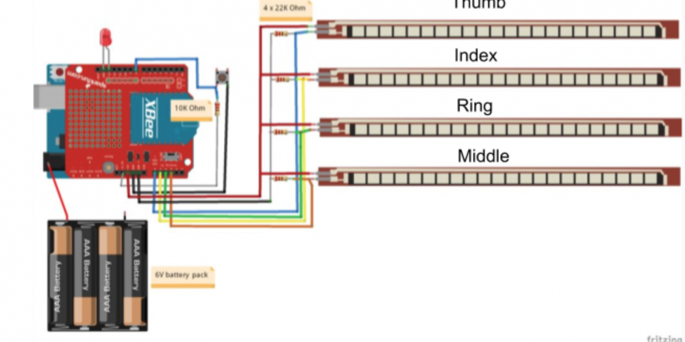
For my second milestone I built the car and arm as well as coded the car. First I connected the motors to the motor driver which allows the motors to move in both directions and have the correct amount of current to flow to the motors. I then connected both servos to the motor driver and arduino. This gives them power, ground and allows you to code them through the arduino. The XBEE shield on top of the arduino connects the XBEE to the arduino allowing the car and glove to communicate. Finally I connected the lithium battery to the motor driver through a switch so I can turn it off and on. The code has two parts the glove code and the car code. On the glove the arduino reads the values of the flex sensors and send it to the car through the XBEE’s. The arduino on the car then assigns those values to being the flex sensors being bent or unbent. I then assigned certain flex sensors being bent to different directions that the car can move. My code says that if I point with my index fingers it goes forward, if all fingers are bent it goes backwards, middle finger bent is to turn right and index and middle bent is to turn left. One problem I encountered while building this was that the gripper and the tilt pan were not compatible so they did not connect. To solve this I made a block of wood that could connect both pieces but also switched to a stronger servo because the one that came with the tilt pan was not strong enough.
First Milestone
Glove Circuit

// Router!
int flexSensorPin1 = A0;
int flexSensorPin2 = A1;
int flexSensorPin3 = A2;
int flexSensorPin4 = A3;
int ledPin=13;
int button=8;
int button_read=0;
int b=0;
int k=0;
char s_str1[2];
char s_str2[2];
char s_str3[2];
char s_str4[2];
char command=’e’;
String str1,str2,str3,str4;
void setup(){
pinMode(button,INPUT); // The button is going to control if we are going to control either the robot arm or the motors.
Serial.begin(9600);
}
void loop(){
if (digitalRead(button) == LOW) // check if button was pressed
{
b++;
b=b%2;
delay(250);
if (b==0){
command=’s’;
digitalWrite(ledPin,HIGH); // indicator on the hand to know if the motors is going to be controlled or the robot arm
}
else {
command=’e’;
digitalWrite(ledPin,LOW);
}
}
// Read the values
int flexS1 = analogRead(flexSensorPin1);
int flexS2 = analogRead(flexSensorPin2);
int flexS3 = analogRead(flexSensorPin3);
int flexS4 = analogRead(flexSensorPin4);
// Numbers below is individual for each of the flex sensors
if (flexS1 < 500) flexS1 = 500;
else if (flexS1 > 600) flexS1 = 600;
if (flexS2 < 390) flexS2 = 390;
else if (flexS2 > 450) flexS2 = 450;
if (flexS3 < 520) flexS3 = 520;
else if (flexS3 > 650) flexS3 = 650;
if (flexS4 < 460) flexS4 = 460;
else if (flexS4 > 660) flexS4 = 660;
// Mapping all the sensor values down between 0-9. (0 = full bent, 9 = unbent)
int flex_1_0to100 = map(flexS1, 600, 500, 9, 0);
int flex_2_0to100 = map(flexS2, 450, 390, 9, 0);
int flex_3_0to100 = map(flexS3, 650, 520, 9, 0);
int flex_4_0to100 = map(flexS4, 640, 460, 9, 0);
// Converting all strings to a single char
str1=String(flex_1_0to100);
str1.toCharArray(s_str1,2);
str2=String(flex_2_0to100);
str2.toCharArray(s_str2,2);
str3=String(flex_3_0to100);
str3.toCharArray(s_str3,2);
str4=String(flex_4_0to100);
str4.toCharArray(s_str4,2);
if (command==’e’){
// Send all values to coordinator
Serial.print(“e”); // Indicates the start of the message (e=motors, s=robot arm)
Serial.print(s_str4);
Serial.print(s_str2);
Serial.print(s_str3);
Serial.print(s_str1);
delay(50);
}
else if (command==’s’){
//Send all values to coordinator
Serial.print(“s”); // Indicates the start of the message (e=motors, s=robot arm)
Serial.print(s_str4);
Serial.print(s_str2);
Serial.print(s_str3);
Serial.print(s_str1);
delay(50);
}
}


