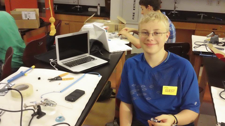
My name is Ian M; I am a rising Sophomore at Hendrick Hudson High school and I built the Forearm Computer. I chose this because I wanted to learn how to code and this required a large amount of it. I enjoyed this project but it was very tedious and the smallest issue could cause problems that would not allow the whole project to work. Within this project their is a humidity sensor, compass, LUX sensor and temperature sensor.
Update: I have added a GPS that has elevation and Clock to this project as well as making it more aesthetically pleasing.
Final Milestone
Circuit Diagram: FC Design_bb
Bill of Materials: https://docs.google.com/spreadsheets/d/11C10YRsyJ3ML2BaquLDrNArWF6cftrGo0QCG3fnXDeU/edit#gid=0
Second Milestone
For my second milestone I completed to get every sensor to work individually and display its data on the screen then from their I got them to work on a button then I combined the codes and got the sensors, buttons and screen to work on a bread board. Once that was working I soldered them all together.
Problems: Some of the problems I faced was the soldering and over heating the board. I happened to of over heated pad 29 on the Teensy microcontroller and this resulted in it falling of. The reason this happened was the compass and the Lux sensor shared a pin so I had to find a new pin/pad to place it.
It works by the Arduino will send a command to the sensors to relay their data back to the Arduino. Once a button is pressed a certain sensor’s data will be displayed to the screen in RH or Lux or Degrees. This is all powered by a 3.7V lithium ion rechargeable battery.
First Milestone
My main project is the integrated sensor electronic bracer. For my first milestone, I planned to accomplish getting one sensor to work and display its data to the display. I accomplished this using the HMC6352 which is a digital compass.
The Arduino, or microcontroller, is hooked up to the computer and is the first component to receive the code which is the commands for the components. the code tells the Arduino to ask the compass for data which is shown in degrees and once it has received it, the information is sent to the display.
I encountered problems trying to get the data to show on the display yet I could easily show it in the serial monitor. I solved this by using my original example display code and transfer the required parts with some modifications. Some of the most challenging parts was to get my libraries properly downloaded onto my computer and get my code to recognize them. I did so by editing the beginning of the code to recognize the libraries. I also had to learn lots about the basics of coding to get my code to work correctly with no errors.
The compass works by using the strongest magnetic field (the poles) and when the compass is at 0° it is facing directly north (180° South).
The compass is first wired to the Arduino “http://wiring.org.co/learning/libraries/hmc6352sparkfun.html” and the Arduino is wired to the display “https://learn.adafruit.com/monochrome-oled-breakouts/wiring-1-dot-3-128×64”
Starter Project (TV B Gone, By Cornfield electronics)
http://www.adafruit.com/products/73
The TV B Gone is a universal remote control that is programmed to turn off any TV by sending out every power down frequency for a remote control using infrared waves (in North American/Asia/Europe/UK).
“How It Works”
Once the button is pressed a signal is sent to the microcontroller which initiates the process and sends a signal to transistors which switches on the LED’s to emit the IR signals to go the the TV. The various signals are emitted for two continuous minutes.


The only problems I encountered was the orientation of the parts. (It does not work if it is not orientated correctly)


