LED Binary Clock
I am doing an LED binary clock for my main project. Although this is a simple two-week project, it provides plenty of room for modifications, which is the reason why I choose to build this.
Engineer
Hugo L.
Area of Interest
Material Engineering
MileStone Two/Final
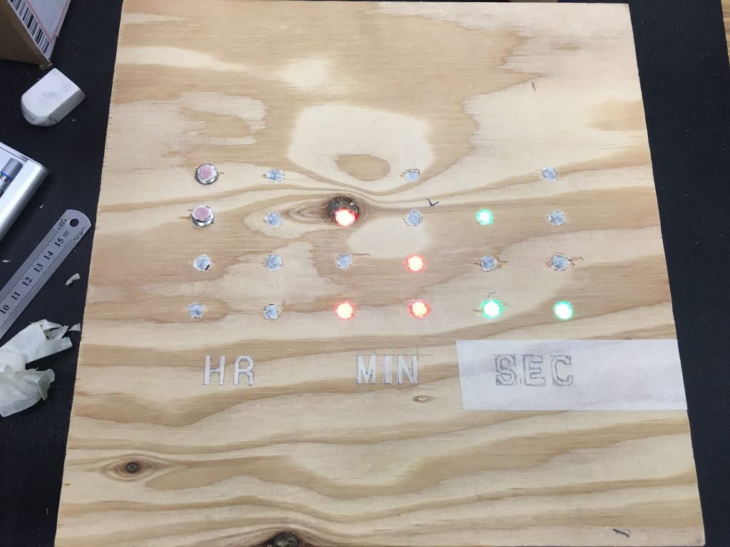
This is my second and the last milestone for my project. In two weeks, I built a binary clock mounted on a wood box and it looked awesome. I had my finished prototype at my first milestone, since then I mainly worked on modifying my wood board, soldering wires, and making the wood box.
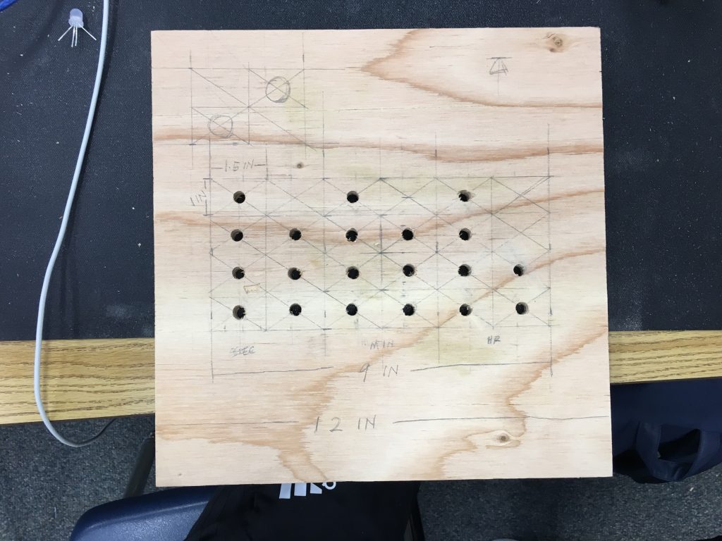
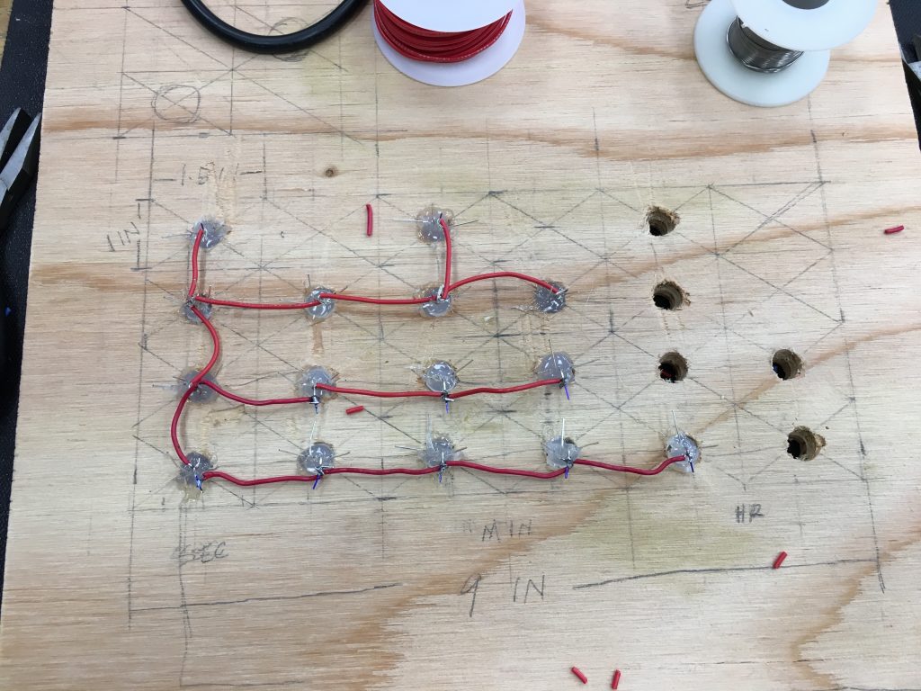
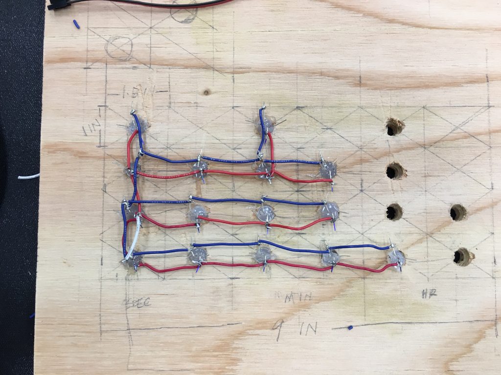
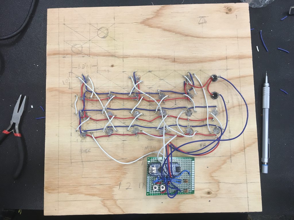
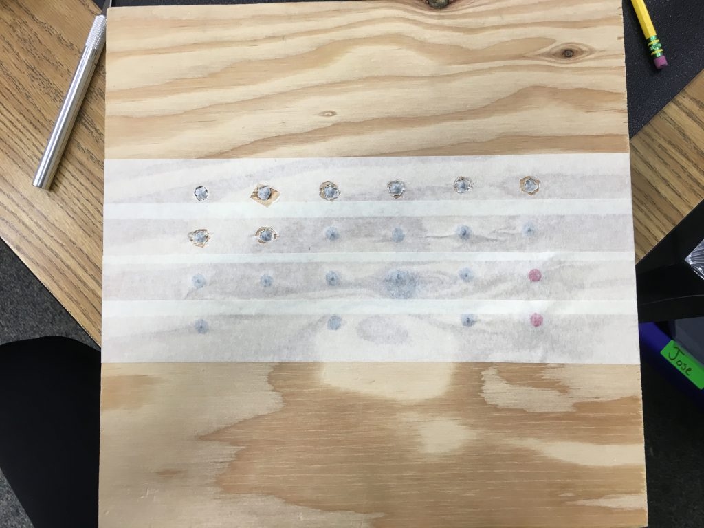
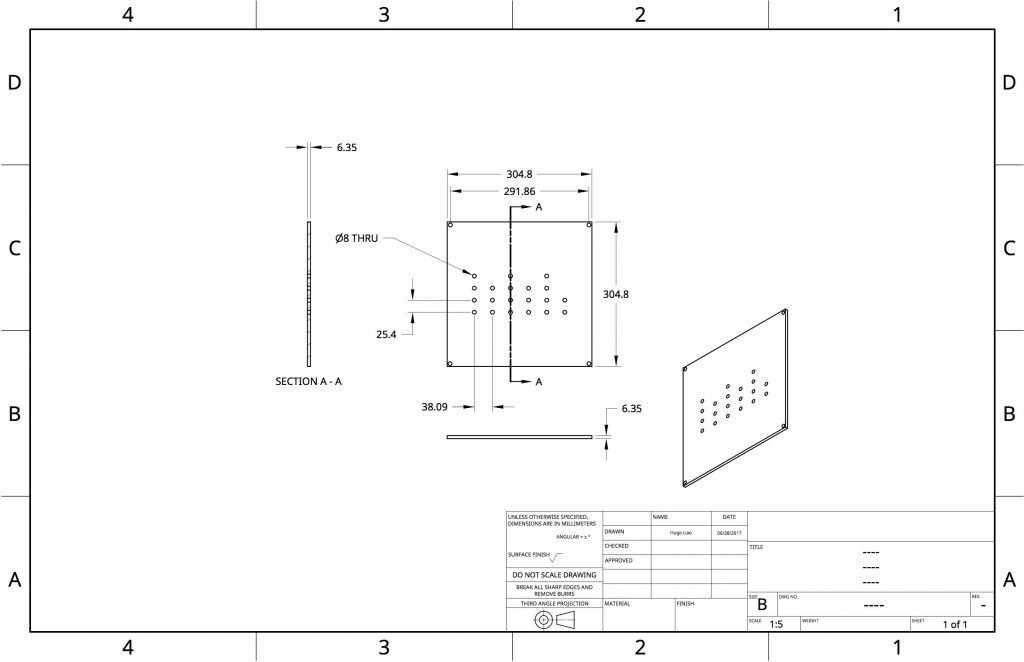
For the wood board, I drill 20 holes for the 20 LEDs. I used NeoPixels from Adafruit for my project. They are 8 millimeters (0.314961 inch) in diameter for the top and 10 millimeters (0.393701 inch) for the bottom. I drilled 8 mm holes first, and then counter-drilled 10 mm holes for the base, so that the NeoPixels could fit perfectly reaching the other side of the board. Then I used hot glue to fix them in place. After that I solder all the components together using different colored wires to make sure I would not make mistakes.
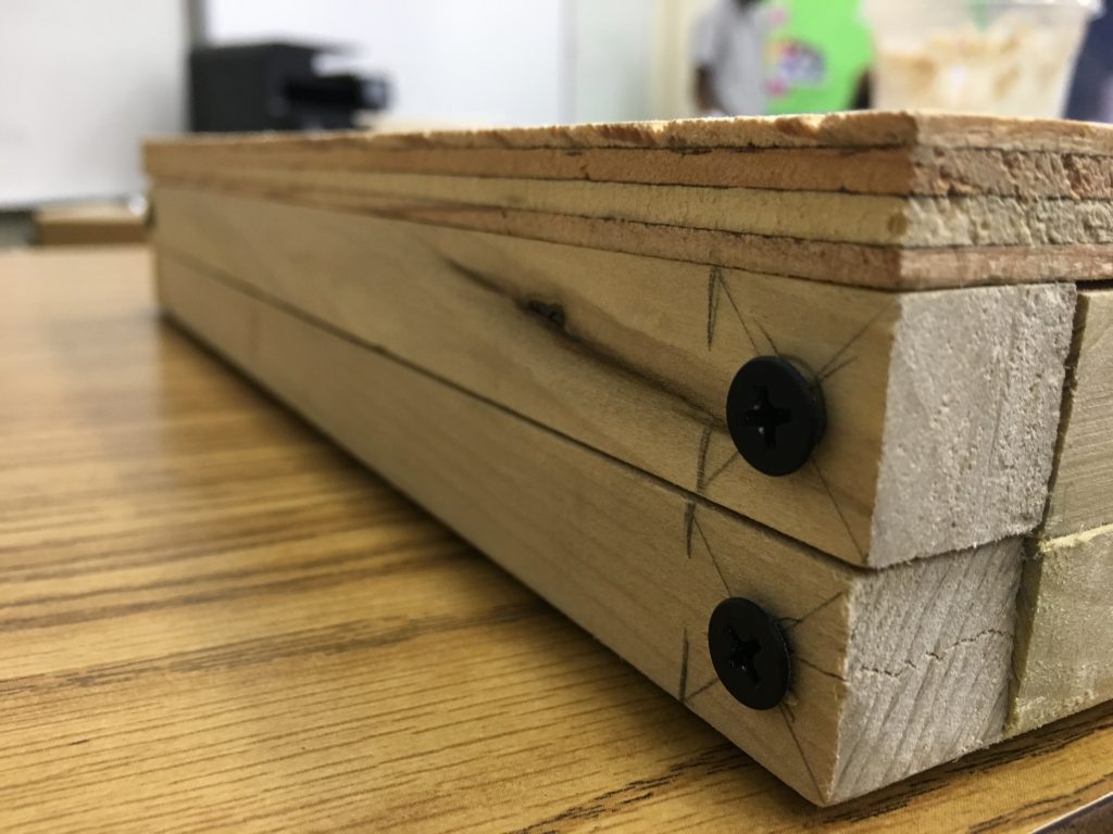
Manufacturing the wood box took most of my time. Even though I only attached two levels of wood strips on the back of the wood board to turn it into a box, the power drilling and screwing was very difficult. If I were to do this project again, I would make sure I have a good design that requires the least amount of drilling/work while achieving the most.
After I finish my wood box, my project was pretty much done. However, I decided to spray paint it in black to have a cooler/ more mean appearance.
Overall, this was a very simple project, I was able to keep myself up with the schedule. The biggest struggle would be having to do a lot of soldering, which required a ton of concentration. For anyone who is interested in doing this project, a friendly reminder would be getting prepared for dealing with electronics and soldering. Lastly, have fun!
Modifications
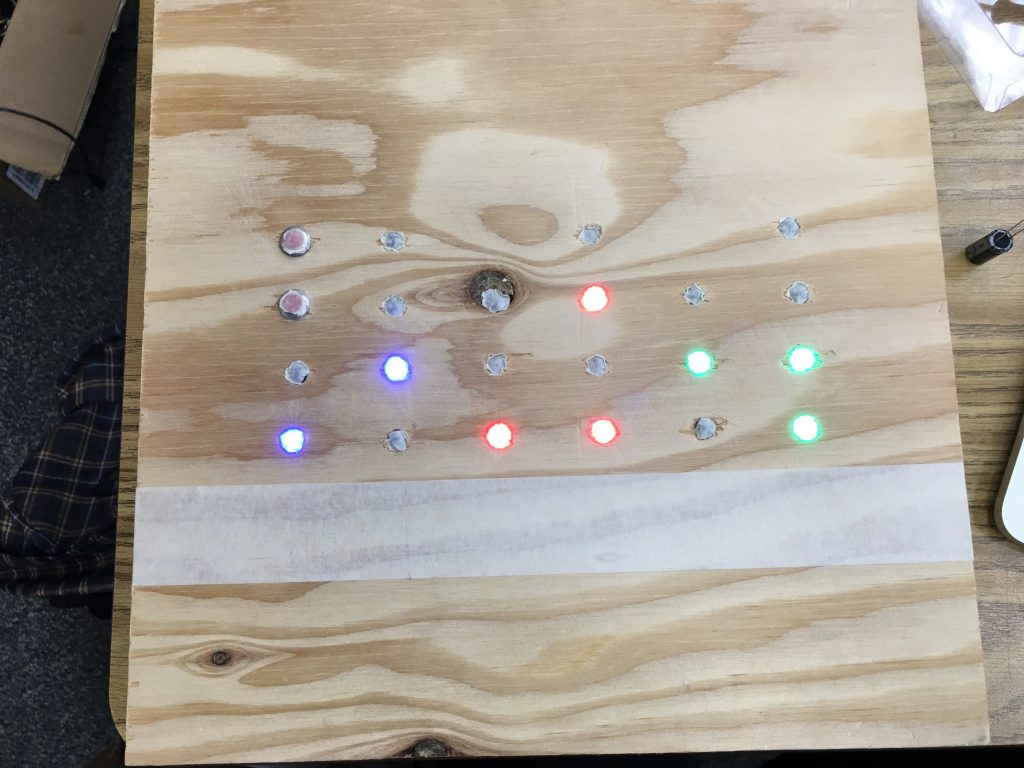
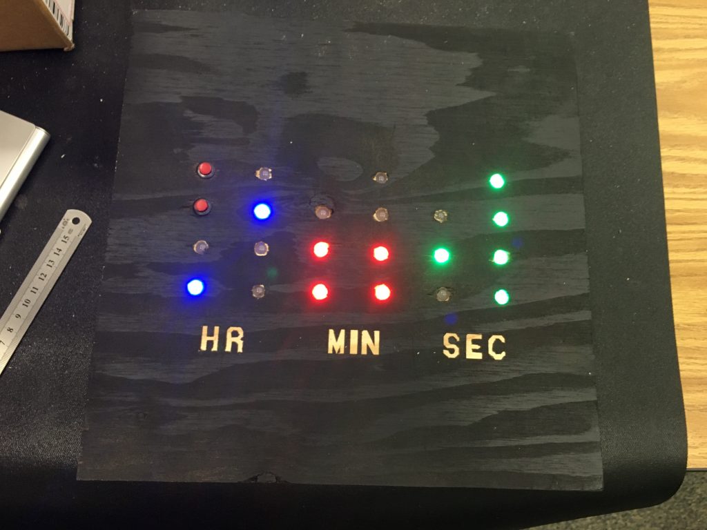
I added two buttons for modifications on my binary clock. Both buttons are mounted on the front of the binary clock. One button turns the clock to a lamp by turning all the LEDs to white; the other changes the brightness of the clock. The clock has three levels for brightness: full brightness(255), dimmer for night mode(50), and off(0). The video below demonstrates how they work.
Binary_Clock_Done
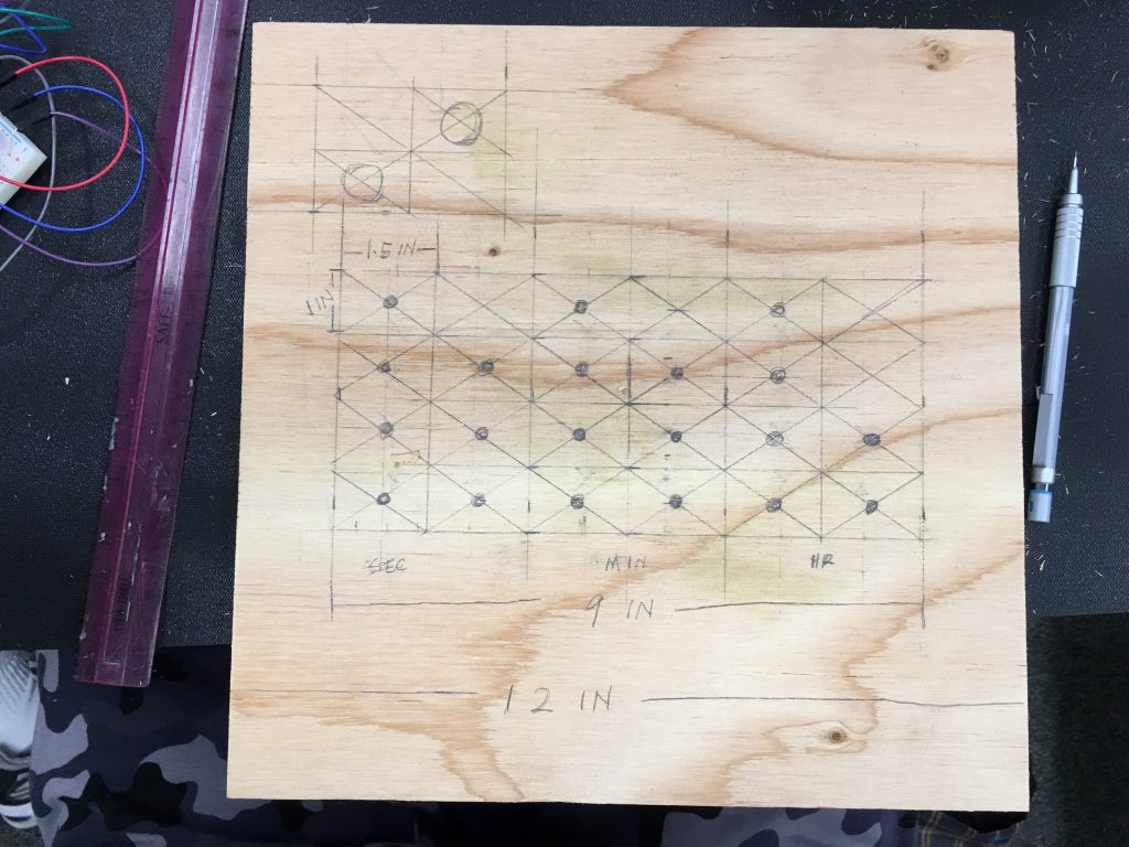
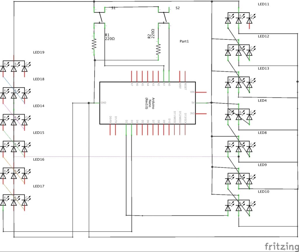
Mechanical Drawings
MileStone One
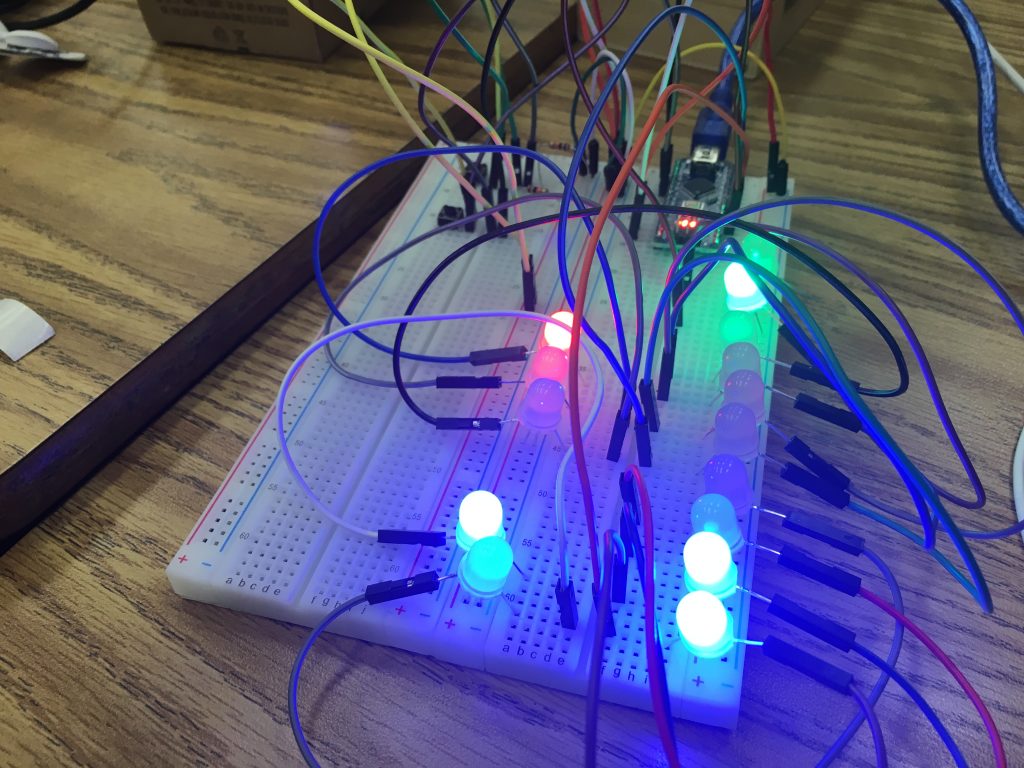
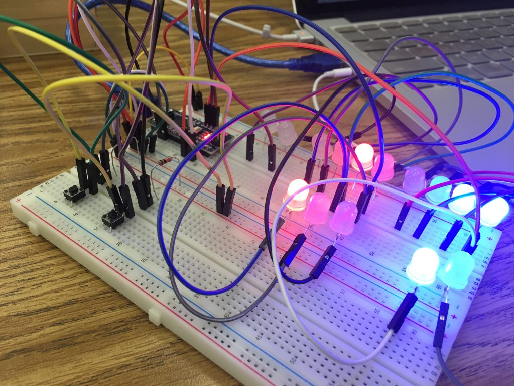
At my first milestone, I am able to finish a prototype of a binary clock. I have connected all the LEDs and buttons that are essential for this clock, and a complete code uploaded to the Arduino Nano. Until my next Milestone, I am going to work on doing modifications on the binary clock, as well as modifying my plywood boards so that I can mount my clock on it.
For this project, so far I have used 15 LEDs in total, an Arduino Nano board, two buttons, two resistors, and wires. I am using NeoPixels for my LEDs, which are pretty handy for this specific project as they require much less wiring and can display multiple colors. All NeoPixels are connected to 5V power supply and ground, and are chained via their digital I/O pins. This means that they are always powered while lighting up according to digital signal sent from the board. Therefore, wiring is simple for me in this project, yet figuring out how to control each individual pixel on the strip of LED becomes the challenge. However, I am able to solve this by researching online and changing lines of code.
Overall, I think I am very close to completion, yet I have only spent a couple of days on this two-week project, thus I think this is a great project for starters.
binary clock prototype
Starter Project
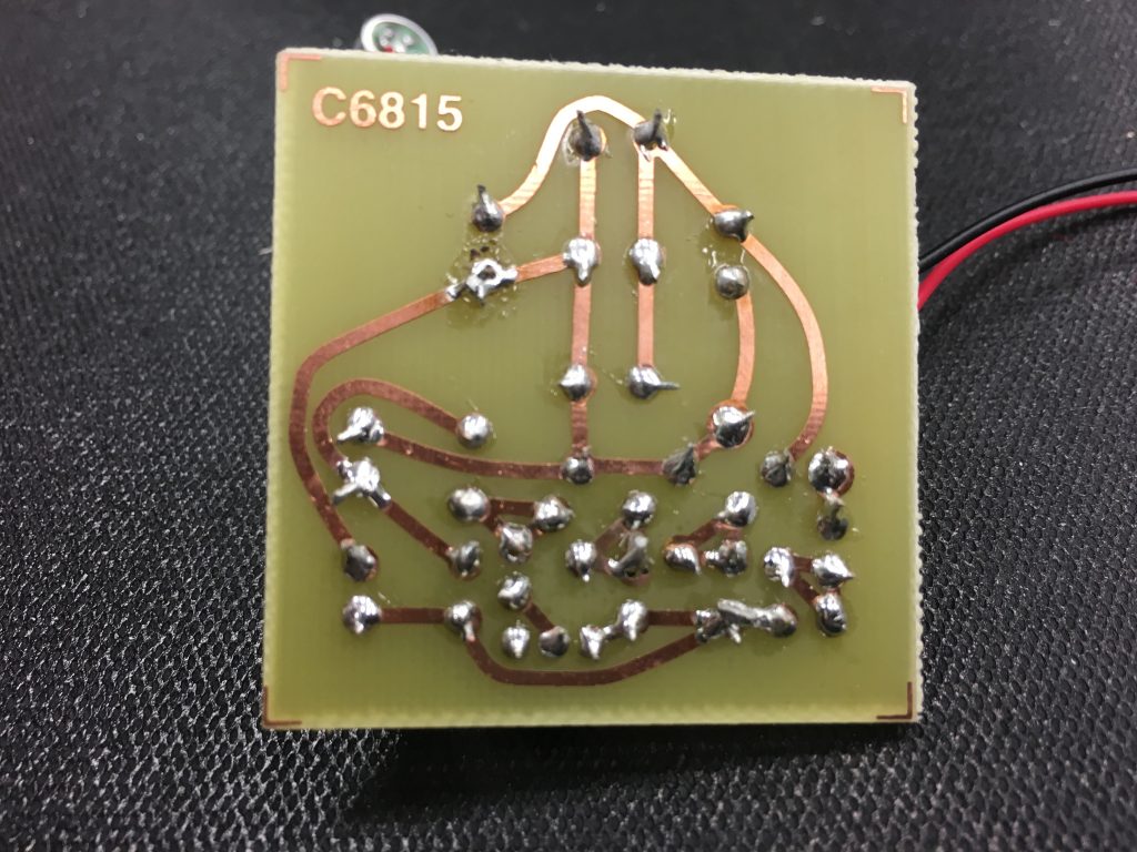
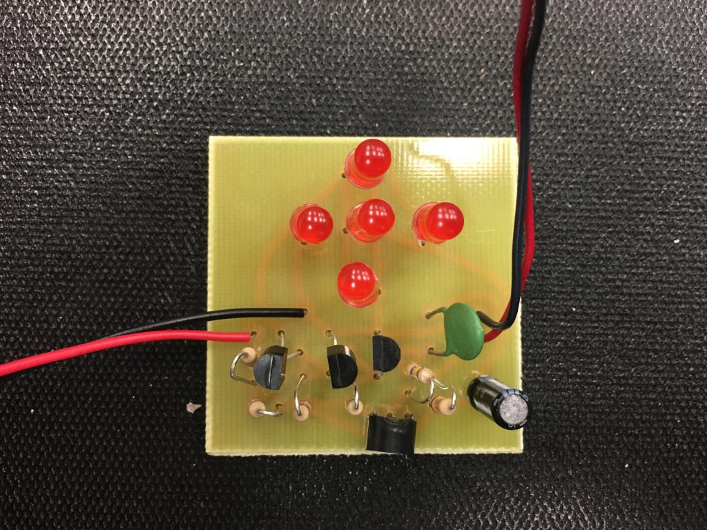
For my starter project, I made a light organ, which essentially is a group a LEDs that light up according to sound inputs.
It was my first time soldering when I did this project, I learnt how to solder and solder worked on a circuit board. While I solder different components, I learnt a lot about electrics as well. I learnt the purpose of inductors, capacitors, diodes, resistors, and microphones. I also learnt how to distinguish between different types of each component, as well as how to read the complex/confusing labels on each component and determine its volume. This was a rather simple project, and the only problem I encountered was to make sure that I soldered everything properly. The most challenging part was to research and understand what each component did on the circuit as well as why they were necessary.
In the video, I will explain what each components do based on my understanding.