FM Radio
The FM radio is a small, portable radio that accesses signals from 88-108MHz. It has two switches – one to scan up in frequency and one to reset the frequency to the starting value – as well as a potentiometer which acts as a power switch and volume knob. I built the radio and then added modifications so I could personalize and improve it.
Engineer
Henry F
Area of Interest
Electrical Engineering / Music Engineering
School
The Urban School
Grade
Incoming Senior
Second Milestone
For my Second Milestone, I made the radio compatible with my distance sensor. I wrote code which activates the radio when the sensor detects an object within a certain distance. If there isn’t an object within a certain distance after a certain amount of time, the radio will turn off. The hardest part for me was figuring out how to wire the radio to the transistor so that I didn’t accidentally overload the radio.
In order to connect the motion sensor to the radio, I needed to use a MOSFET transistor so I could control the radio through the Arduino. MOSFET transistors feature three pins: the gate, the drain, and the source. The gate is connected to pin 9 in the Arduino – this is how the Arduino controls the radio. The drain is connected to the negative side of the battery in the radio, and the source is connected to the 5V output in the Arduino. In this way, the Arduino can control the power output through the transistor to the radio.

First Milestone
My first milestone was creating the actual radio. I soldered on parts to a printed circuit board, or PCB. A PCB has copper paths on it which let you solder parts together without having to create the connections yourself, so it allowed me to not worry about how to connect the parts together. I ran into issues when I ripped up some of the copper lining, essentially ruining connections between certain parts. To fix this, I put on excess solder so that it held the copper lining down. As a result, the board looked less organized, but the connections worked.
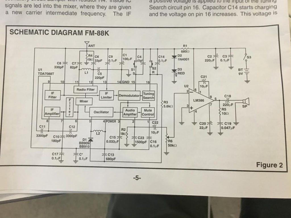
The main component of the radio is the integrated circuit chip (IC chip) that comes on the PCB board. It features an oscillator, demodulator and mixer, which take and refine signals so it can produce sound from radio stations. The oscillator is an independent circuit that creates a continuing sine wave. The mixer takes these signals and creates new frequencies from them, and the demodulator is a circuit that extracts information from a modulated sound wave
Circuit Diagram
Starter Project
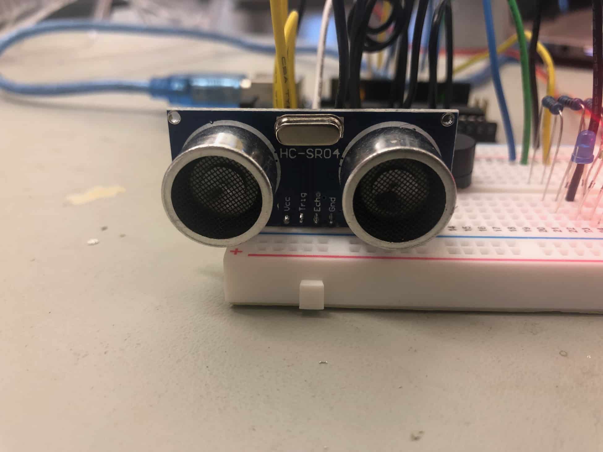
My starter project is the distance alarm. It’s comprised of an ultrasonic sensor, buzzer/speaker, pin wires, an Arduino, and a breadboard. Unlike a motion alarm, the main function of the distance alarm is to detect if anything is within a certain distance, while the motion alarm will only report data if something is actively moving in a certain distance.
How it works
The distance alarm works through an ultrasonic sensor with one speaker and one mic. It sends out ultrasonic sound waves from the speaker that bounce off an object and get reflected back to the mic. The sensor times how long it takes for the signal to come back, essentially producing data for how far away an object is (basically echolocation). My Arduino program records this data and, if the value the sensor picks up is below a certain time (or distance), activates the speaker to play a sound.