
Gesture-Controlled Robot
The gesture-controlled robot involves a small glove-type component, which goes in the hand, and the robot, which is a car made with arduino that moves in response to the gesture. As the user tilts his/her hand while wearing the glove, the car will move in the direction of the tilt. The car can also accelerate forward or backward depending on the incline of the tilt.
Engineer
Harshil G
Area of Interest
Chemical Engineering / History
School
The Harker School
Grade
Rising Junior
Third Milestone
My third milestone was to finish connecting the gesture control to the car and making it work. I programmed the accelerometer to receive the pitch data (the data of how much I tilt the accelerometer forward & backward), and I used that data to move the car forward and backward. The data is transmitted from the gesture control to the car via the NRF modules. In response, the car moves forward if the pitch is positive, and the car moves backward if the pitch is negative. The speed of the car is proportional to the acceleration of the accelerometer.
Here is a video in which I demo my project. While there are a few bugs that prevent it from moving efficiently, the car roughly moves in response to my hand gestures.
Second Milestone
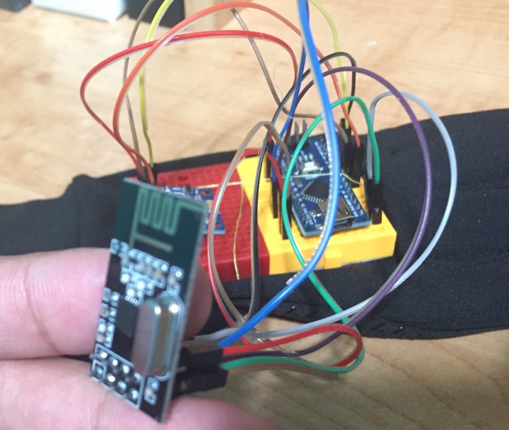
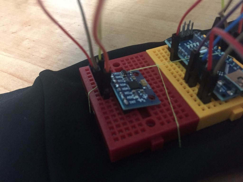
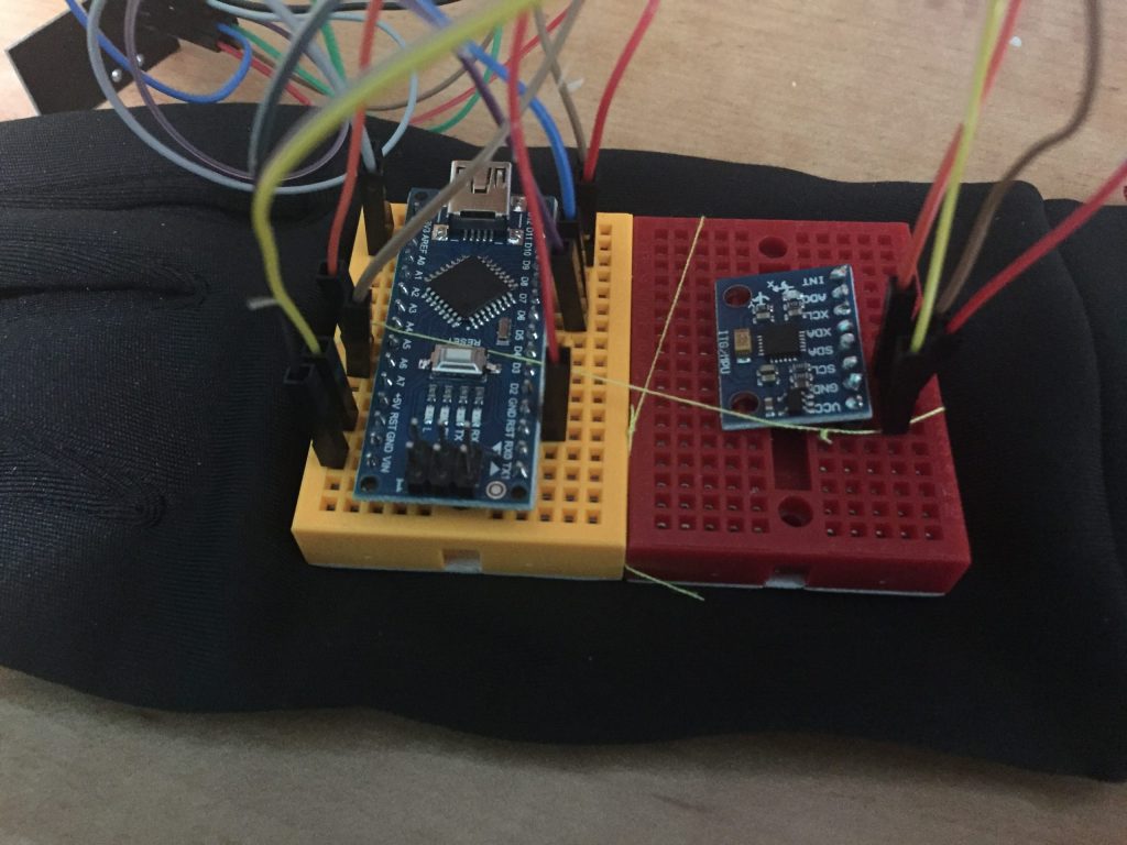
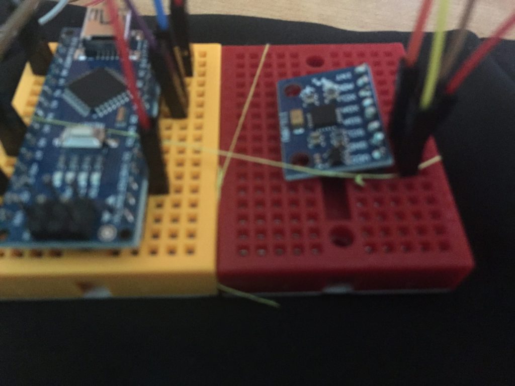
My second milestone was to finish assembling the gesture control. I used a breadboard as the base. First, I put the arduino nano onto the breadboard. Next, I connected the NRF module to the arduino breadboard. This required connecting 7 wires from the NRF module to specific pins of the arduino nano. After that, I soldered the accelerometer to some pins, which I put on the breadboard. I connected 4 wires from the accelerometer to specific pins of the arduino nano. Finally, I sewed the breadboard to the glove.
Soldering, Wiring, and Assembling the Gesture Control
My first task was to connect the NRF module to the arduino nano and make it work. This was difficult as it required connecting 7 wires to specific pins of the arduino nano. The website I used contained the incorrect wiring, so I spent most of my time trying to figure out why the NRF module was not working: I checked whether the wires were working, and I also checked whether the arduino was working. Finally, after figuring out the correct wiring, I successfully connected the NRF module to the arduino nano. There is also an NRF module connected the arduino uno on the car, and the NRF module on the gesture control sends radio messages to the NRF module on the car, which is how the gesture control actually controls the car. Next, I had to solder the accelerometer onto some pins. I first practiced soldering some resistors to other circuit boards, then I soldered the accelerometer to 8 pins. I made a small mistake, so I had to remove some solder with a copper strip, but I eventually succeeded. I connected 4 wires from the accelerometer to specific pins of the arduino nano. Finally, I had to sew the breadboard (in which all of the pieces were on) onto the glove because I will be wearing the glove as I control the car. I wrapped the breadboard horizontally and vertically with thread.
First Milestone
My first milestone for the Gesture-controlled Robot is to make the car and get it to move. I built the car chassis and put the motors on it. I also finished the wiring of the car. I had to use three electronic components: the motor driver, the Arduino Uno, and the battery pack. I connected the motor driver to the motors, the battery pack, and the Arduino Uno. Furthermore, I started coding and got the car to move.
The Car Chassis
The first step in building the car was assembling the car chassis. The chassis consisted of two circular metal pieces that go at the top and bottom of the chassis as well as two motors, two small metal pieces, a ball bearing, and some screws. I first put the two small metal pieces on one of the large circular pieces. I then put the motors on the large circular piece, which I secured with a screw to the small metal pieces. I then screwed the ball bearing to the bottom of the chassis. Finally, I put the larger screws between the bottom and the top of the chassis, and I put the top of the chassis later on, securing it to the screws.

Completing the Wiring
Completing the wiring the proper way is essential to making the car move. The DF-MD V1.3 motor driver is at the center of the circuit, and all the other components (motors, battery pack, arduino board) are connected to the motor driver.
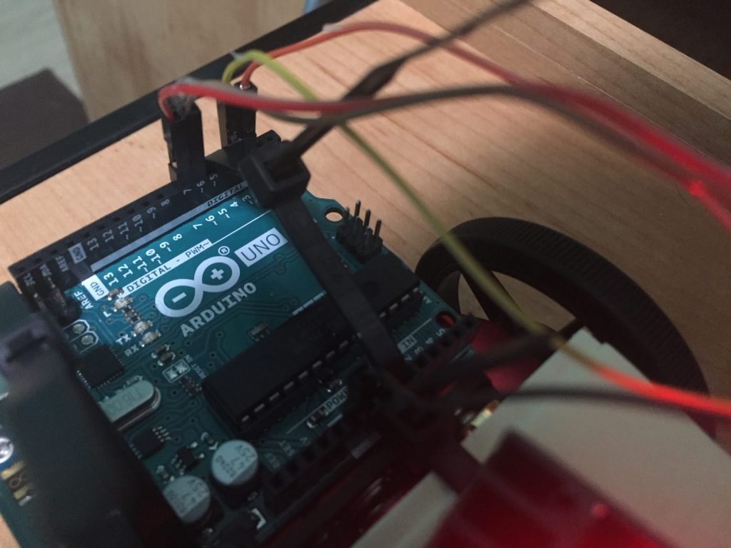
The 2 motors need to be connected to the 2 motor terminals in the motor driver. One wire from the battery pack needs to be connected to the ground terminal of the motor driver, while the other wire of the battery pack must be connected to the lower voltage power terminal of the motor driver. Finally, the 4 motor control pins in the motor driver must be connected to the arduino board. The 4 motor control pins are arranged in 2 pairs of 2, and each pair has an analog pin and a digital pin. The analog pin must be connected to the pins indicated by a tilde (~) on the arduino, while the digital pins must be connected to the other pins on the arduino. Furthermore, a wire must connect the ground terminal of the motor driver to the ground pin of the arduino.
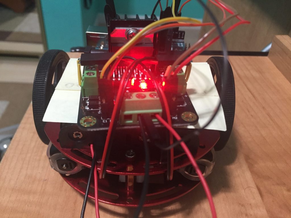
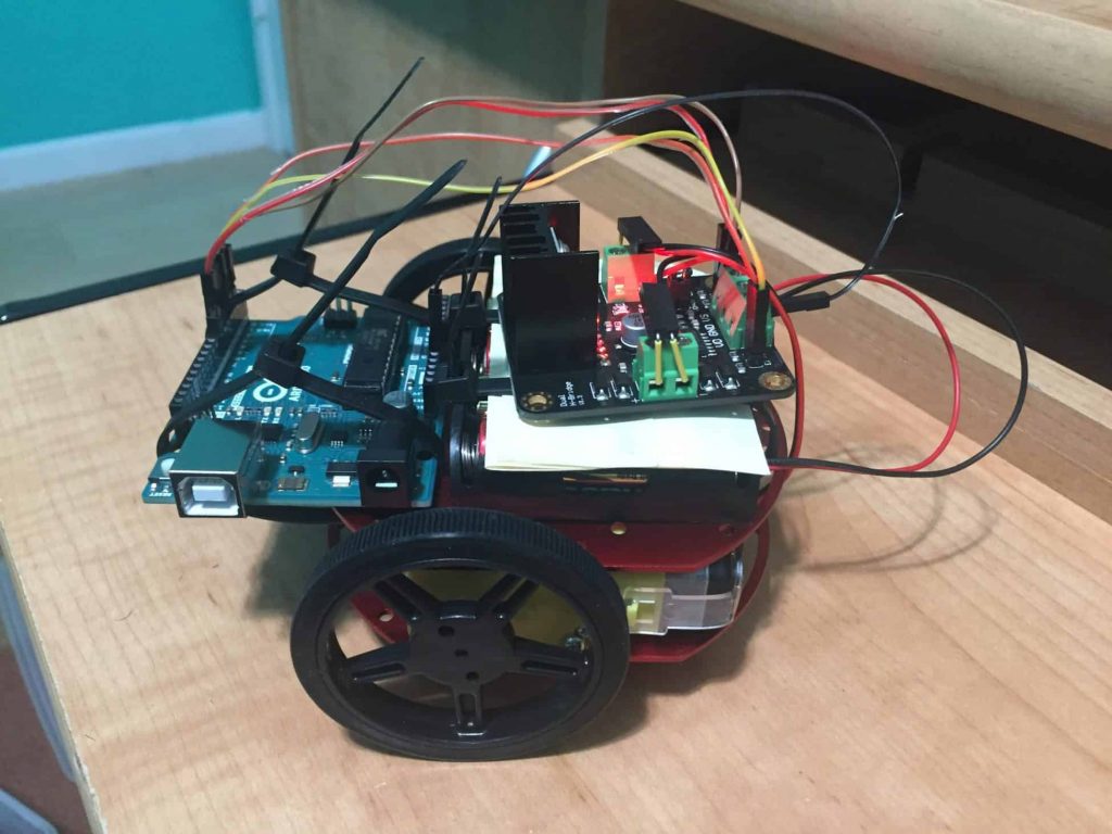
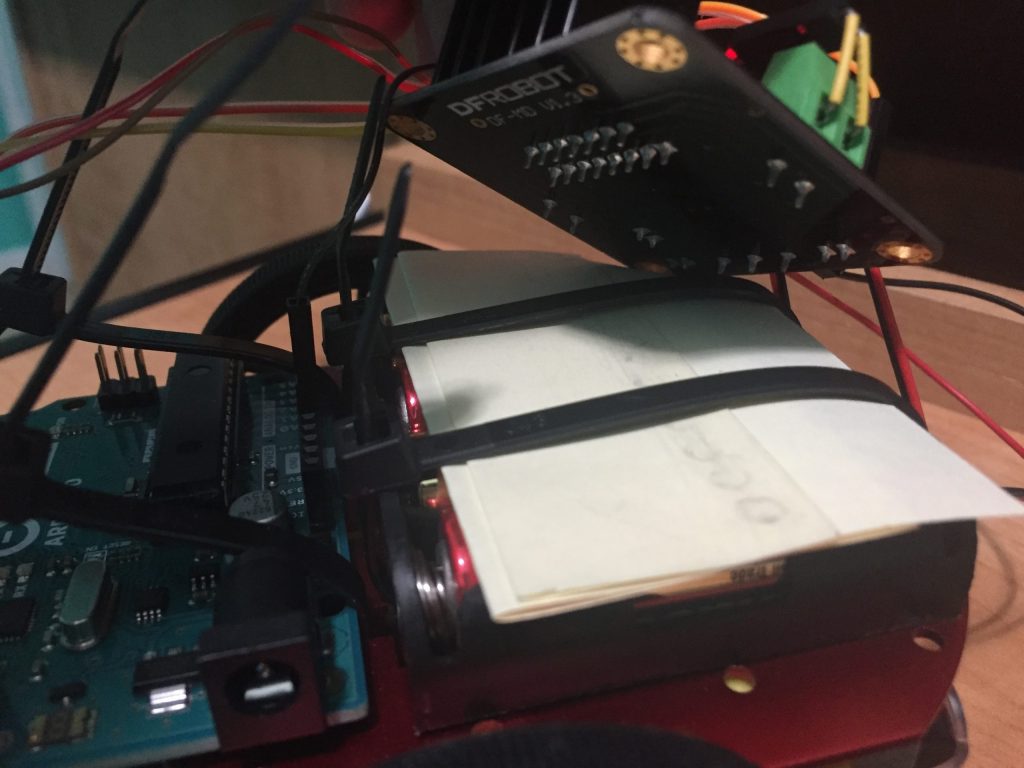
The next challenge is placing the 3 components on the car chassis given the limited space. My plan was to put the battery pack and arduino back-to-back on the chassis while putting the motor driver on top of the battery pack. I made the mistake of using cellophane tape to secure the battery pack to the chassis. Since the cellophane tape conducts electricity and part of the tape was connected between positive and negative terminals of the batteries, the tape created a short circuit as the electricity would move from one terminal to another without any resistance. This created some smoke, and when I touched the tape to remove it, my finger got slightly burned. Thus, I used a screwdriver like a spoon and removed the batteries from the battery pack and later removed the tape. Thus, I used zip ties to secure the battery pack and arduino board to the car chassis. To put the motor driver on the battery pack, I had to put post-it notes above the battery pack to prevent a short circuit between the battery pack and motor driver. Since the motor driver has metal pieces sticking out the bottom, a short circuit could easily created when those metal pieces touch the batteries, so I had to block it with post-it notes.
Testing the Arduino Code
const int E1 = 3 ; // E1
const int M1 = 2 ; // M1
const int E2 = 6 ; // E2
const int M2 = 7 ; // M2
void setup() {
// put your setup code here, to run once:
pinMode(E1,OUTPUT) ;
pinMode(M1,OUTPUT) ;
pinMode(E2,OUTPUT) ;
pinMode(M2,OUTPUT) ;
digitalWrite(M1,LOW) ;
digitalWrite(M2,HIGH) ;
analogWrite(E1,100) ;
analogWrite(E2,100) ;
delay(300);
analogWrite(E1,0);
analogWrite(E2,0);
}
void loop() {
// put your main code here, to run repeatedly:
}