
My name is Hadassah and I’m a rising junior at the Ramaz Upper School. As an avid reader, I have always found myself wondering about the sci-fi creations invented in the minds of authors. Were they possible? Was this the future of the world, I wondered? And so began my journey into engineering and my genuine interest in conserving the world through technology.
SBOT
The Sustainable Robot Dog
SBOT is a multifunctional robot constructed of recycled material. He moves on command. He additionally displays the time in an attached LED alarm clock. He will continue to learn new tricks throughout his doggy life. For a detailed description of what his functions are and how they work visit sbot, the recycled robot at instructables.com. Woof.
The wind lantern uses a turbine that spins in the wind and generates energy for use in a circuit (explained in detail above). It is a combination of both engineering work and environmental sustainability. My hope is that this project will act as an introduction to the engineering world so new to me, as well as continue my activism in environmental conservation throughout the summer.
Wind Lantern Final Video

Inefficiencies
Although the wind lantern does work for its purpose, there are various inefficiencies that would make it unfit for large scale production. The stepper motor, although inexpensive, is not the best choice for a smooth movement that maximizes the amount of energy it can produce. Although DC motors are more efficient at high speeds, they would produce barely anything at low speeds and are therefore ineffective for this purpose.Along those same lines, the gears are rather ineffective, as it is difficult to line them up exactly and permanently glue them in that arrangement. Additionally, had I done the math for gear ratios, it is possible I would have found better fit sizes for gear that mesh much more easily than the two I utilized in this project. The potentiometer eats up much of the voltage when its resistance is high and the lights are low. Additionally, the minty boost when being used eats up the current as it must boost the voltage from 3.7v to 5v for charging items.
Modifications
After finishing the lantern assembly, I turned to modifications for making the lamp more efficient.The first change was replacing the capacitor bank with a 3.7 Volt emitting rechargeable lithium ion battery (consistent with the needs of LEDs 5mm about 3-4 V inputs) so that the lights can stay on when the wind isn’t blowing, for extended amounts of time. The lithium ion battery required a charging circuit, a shield circuit, and ac to dc converting circuit. I therefore changed the original circuit design to include, the rectifying diodes, followed by a single capacitor, and a charging shield unit (from Sparkfun, USB LiPoly Charge-Single Cell, part 12711). The output of the charging cell was, two capacitors, a switch, and 6 LEDs drilled into the bottom disk of the lantern with wiring.

LEDs drilled into bottom disk

Circuitry in Project Box with switch, minty boost, LEDs, and solar panel
For aesthetic purposes, I cut out a 25 by 4 inch piece of diffuser paper to cover the lower base, hiding all the wiring and giving the LEDs a glow to them. The next modification joined a 3 volt DC mini solar panel to the input power supply (the charger provided space for two inputs to combine), upping the voltage and battery charge time. Additionally, a minty boost was added to the output for boosting the voltage to 5V and including an attached USB female connector. With this attachment, a phone could be charged through a USB cord in addition to the LEDs lighting up on command of the switch.I did have some difficulty in adding the minty boost output, as it quickly drained the battery. After some research though, I realized the lithium ion battery I installed has a potential of 1000mAh, which when charged can almost fully charge a phone, iPod, or similar device. Unfortunately, I cannot simultaneously charge my phone to the fullest it offers and use the LEDs. In the future, I would switch this battery out for one of higher Amp-hours. A potentiometer was included to vary resistance in the LEDs, creating a dimming light effect.The final modification was the introduction of a charging circuit to determine the voltage going through the battery (i.e. what percentage of charge the battery has reached).This was accomplished with two reference LEDs, one is constantly on, while the other is followed by a zener diode which allows greater currents to flow through when voltage builds up in it. The two LEDs’ brightness can be compared to determine the battery’s charge.
Documentation
Bluestamp Engineering Bill of Materials
Project Instructions from Instructables.com
Personal Documentation Notebook
Schematic:

3rd Milestone

To catch the wind properly, the lantern required sailings to be built. Therefore, a new shaft was tightened on the aluminum rod slightly above the top acrylic disk and glued one acrylic sail holder with epoxy to the shaft collar. 12 inch x 6 inch aluminum sheets were cut out to act as the sails. ½ inch square tabs on all four corners of the sail were created and slipped through the slits in the acrylic sail. The tabs were then folded them and glued with epoxy to keep sturdy in the wind. A shaft collar, the second acrylic sail holder, and another shaft collar were secured and tightened at the top of the aluminum rod. The top tabs were slipped through the slits in the upper sail holder, were folded down and glued with epoxy. The top shaft collars were tightened. When I gave the finished lantern a gentle push, it spun smoothly.
When the switch on the circuit was turned on, the green LED lit up steadily. The project was completed and I now possess my very own wind lantern in my hands.

Sailings and Base

Base Assembly
2nd Milestone
The second half of the Wind Lantern construction involved the building of the mechanical structure of the lamp’s base.
The base of the lamp consisted of two circular acrylic disks (template for printing: <https://thingiverse-production-new.s3.amazonaws.com/assets/8d/98/be/20/8e/vawt_final_ponoko2.svg>)with three 1/2 inch thick, 4 inch wide hex standoffs between them. The hex standoffs were screwed through holes in the disks using a 1/4 inch washer, look washer, followed by a 1/4-20 screw. A flanged sleeve bearing was inserted into the center hole of the bottom acrylic disk (without the four holes in on the side), so it covered the inside of the hole. The bearing was followed by a thrust washer, thrust bearing, and another thrust washer. Atop that two ½ inch shaft collars, one acrylic gear, another 1/2 inch shaft collar, and a flanged sleeve bearing were placed to coat the inside of the top disk. A 1/2 inch wide aluminum rod (18inches in length) was slid in through the entire stack, started at the top disk and ending just before hitting the surface of the table. The bottom an topmost shaft collars were tightened using an allen wrench and the middle shaft collar was brought to the center of the two disks and tightened there.
The stepper motor’s- previously worked with in the circuit- screws were removed and it was secured upside down with an M3 washer, lock washer, and screw in the four holes of the upper disk. Another gear was secured on the stepper motor by a tightened shaft collar (smaller size than previous ones). Both gears, after verified to move together smoothly were glued with epoxy to the shaft collars holding them in place.
1st Milestone
I began working on the wind lantern by designing a schematic for the circuitry in linking the turbine to the LED, building it on the breadboard, and finally transferring the design to a printed circuit board to be sturdily soldered together. The power source of the circuit is a stepper motor with four extending wires. These wires were soldered to the PCB, connecting each set of two adjacent wires together with four diodes between them (two diodes facing the wires with their negative side and two diodes facing the wires with their positive sides). This format creates a rectifying effect, which converts an alternating current into a direct current, so the direction the wind spins the turbine in doesn’t effect its energy harvest. Normally, the alternating current would form a sin graph with high energy points and low energy points, but the rectifier steadies the current to a straight line.

Original Schematic
Connected to ground, I placed 12 capacitors on a separate circuit board in parallel. Capacitors serve to store energy for steady and longer lasting usage. Inside the capacitors, two non-touching metal pieces, with varying materials between, block the charge from passing through and trap them on each end, storing the energy until needed. When in parallel, the voltage each capacitor can hold is the sum voltage storable in the circuit.
The LED, or light emitting diode’s negative end is also connected to ground while the positive is attached to two resistors and a switch. The resistors serve prevent shorting and the LED from blowing. They resist current flower and lower the voltage being sent through the circuit. The switch has to wires electrically connected, but when the switch is turned, they are disconnected and others are connected, ultimately turning the LED on and off, while the rest of the circuit continues to function (including the capacitors).
One issue that concerned me was how much voltage or how fast the current could flow before the capacitors could explode. To test this, I attached a DMM (digital multimeter)’s probes to the negative and positive sides of the capacitors in the circuit. I then placed a drill atop the motor and spun it quite fast. The result: the capacitor’s voltage rose to about 30 volts, but didn’t explode. Instead some of the voltage dissipated until it reached a steady voltage around 18 volts. Through this I deduced that the voltage dissipated through circuit (likely as a result of the rectifiers) once the capacitors reached their maximum potential. Therefore, the wind speed or constancy of wind will not damage the capacitors, even if the lantern is left in high wind conditions for extended periods of time.
If time permits, I will replace the capacitors with a rechargeable battery to conserve even more voltage and power the lantern for longer periods without the presence of wind.

Breadboard Configuration

Completed Circuitry for Wind Turbine

Main PCB with rectifiers and all other wires connecting to materials off the circuit board
MiniPOV3
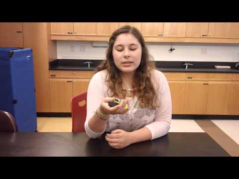
In the past four days, I built and programmed the minipov3 to display a custom message. The first step in the project involved connecting the circuit and soldering the resistors, diodes, micro controller (and its socket), the LED lights, and the wires for the battery holder all to the printed circuit board (PCB). Next, the software to convert the USB to serial port needed to be installed. Lastly, I created a binary code to display my custom message of “Earth” and compiled it.
The minipov is a device that utilizes persistence of vision, which causes multiple stimuli, in this case images, to combine in high speeds, and form a larger image. The flashing sequence of the LEDs (light emitting diodes), programmed by the binary code, when shook really fast displayed a combined image. The resistors prevented the electrical flow from damaging the circuit and the microchip stored the information programmed on the computer.
The instillation of the proper software involved the use of terminal in Mac and later the command prompt on a windows computer. As I had never operated terminal before, I learned some basic commands such as cd (change directory), ls (list what’s in the documentary), pwd (the exact location in which the terminal currently is), clear (clear the terminal page), make program-filename (for creating programs), del or rm (for deleting), run (to run applications), open to open files), type (to view a document in terminal), vi (to edit documents through terminal), etc. Additionally, I became familiar with binary code and discovered the ones represent on and the zeros represent off, basically the two commands the computer understands. Each “one” is really “two” to the power of the number it is in the binary sequence and all the numbers are added together.