Weather Indicator with IoT
The weather IoT device is a device that changes color according to the weather. If there is a change in the weather the device will shine the color that corresponds with the new weather.
Engineer
Gokul N.
Area of Interest
Engineering Management (Mechanical Engineering + Business)
School
Mission San Jose High
Grade
Rising Sophmore
Modification Plans/Reflection of the program
Modification Plans: One of the modifications I completed during the camp was to drill a hole in the lid in order to have the USB cable fit down there instead of a having the lid close on it as before. Another modification I had in mind was to switch the wiring from a breadboard to a perfboard. This will make the wiring more organized and also provide a better connection. A major addition I want to accomplish is adding a LCD screen to the device which displays the weather condition in addition to the temperature. This will be extremely useful as the person looking at the device will be able to identify what weather the color corresponds to. I wasn’t able to get this done on the last week of camp, but I will work on it at home and achieve this.
Reflection: Coming into BlueStamp I had coding experience, but not too much hardware experience. Through completing the 2 week program I am walking out with a better understanding of how electrical components work; while also becoming a better hands on and independent person. BlueStamp has made me love engineering more, and although the program for this year is done I am determined to modify my project and make it better. I aim to come back next year and pick a more challenging project and have another great time with an addition to creating many cool projects outside of camp!
Final Milestone
Notes:
1. In my Final Milestone clip I may have referred to it being my Second Milestone. This was not my Second Milestone, it is my Final Milestone.
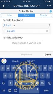
2. In the last couple of seconds in my video I said that I would simulate the weather by entering the keyword onto my phone which would get the device to change color. By this I meant that through particle say I entered the word “Clear” this is the same thing as if IFTTT gave the weather condition as clear to the photon; getting the neopixel ring to display the color corresponding with the condition clear. I did this instead of waiting for the weather condition to change the color because IFTTT only updates the weather condition every 15 minutes and in order for the next update in the video to change the color, I would had have to wait 2 extra minutes.
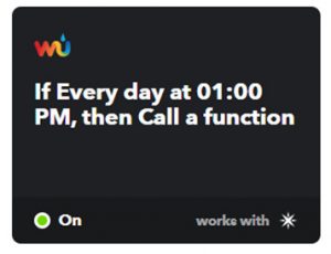
This button below links to a clip in which my weather device reacts to the weather at 1:30 PM. Since it was sunny it was shining green.
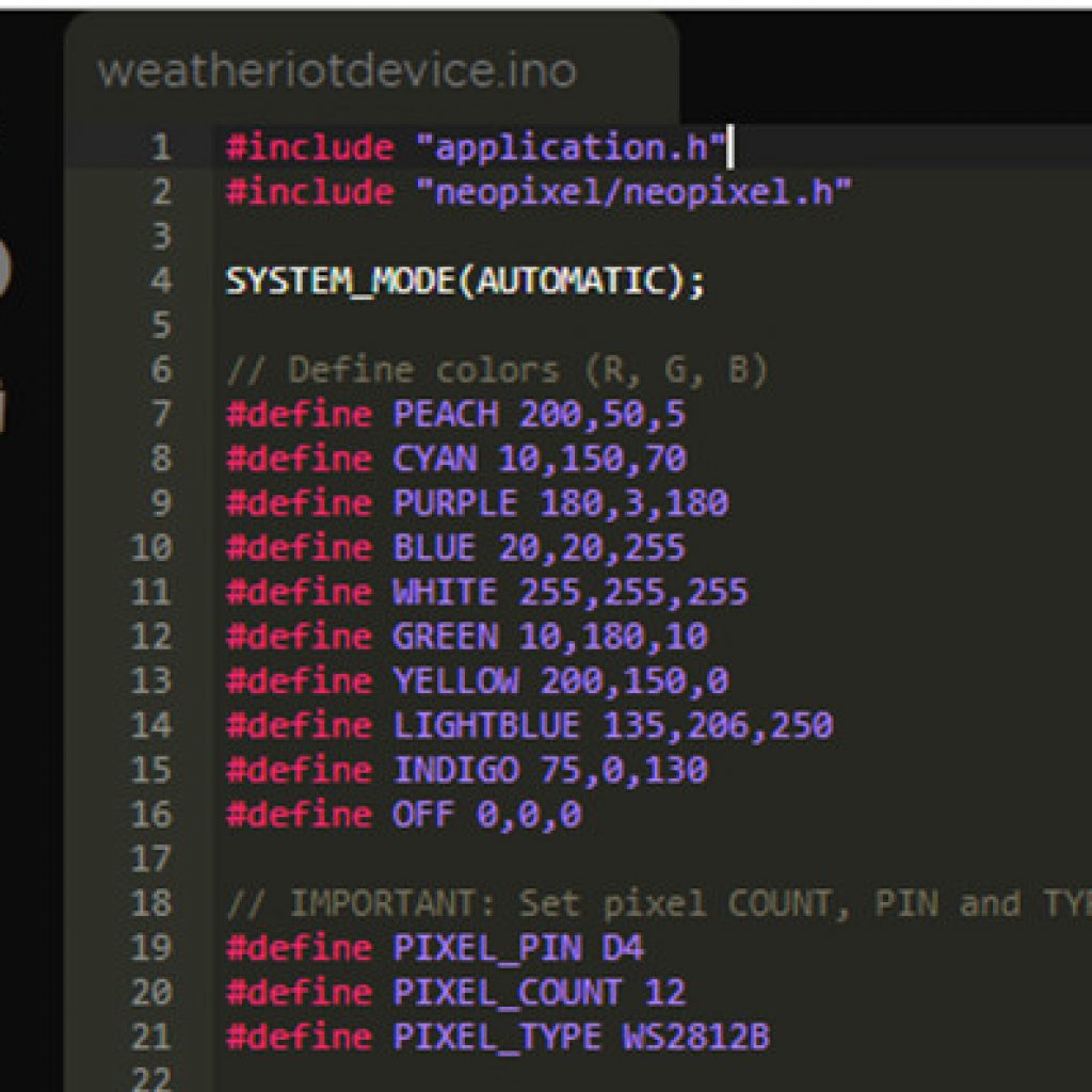
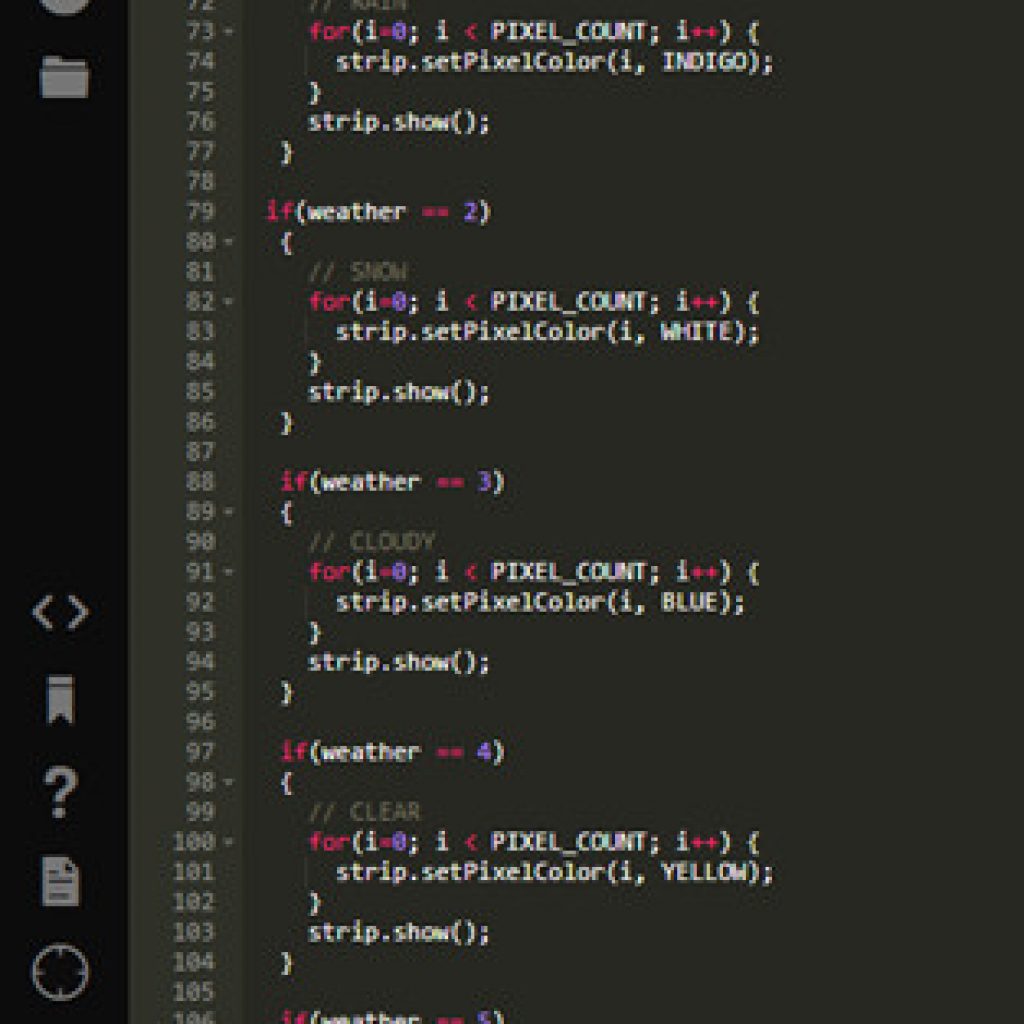
For my final milestone I got the device to change color according to the weather. I used Particle to write my code and IFTTT to get the weather. First on particle I defined all the colors that I wanted to be displayed through the neopixel ring. Then for each of the 7 types of weather conditions I wrote a series of if statements getting the neopixel to display a certain color based on the weather condition. I accessed the weather through an online platform called IFTTT(If This Then That) by writing triggers called applets. At first I wrote a type of trigger that only recalls the function when there is a change in weather. In California, especially during summer, it is always sunny so I had to think of a different way for the device to work. One solution was setting the applet to the Weather Report Mode. The Weather Report Mode will return the corresponding color of the weather at a certain time. This turned out to be a success! I am also able to simulate the weather through the Particle App on my phone in order to change the color displayed by the device.
First Milestone
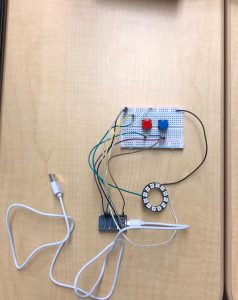
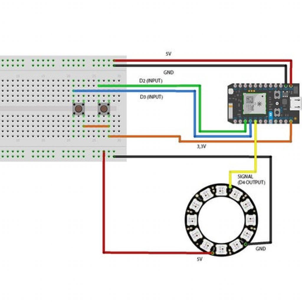
My first milestone is being able to manually change the colors with 2 momentary switches. I first made connections between ground on the neopixel ring and the ground pin on the photon. Then I made a connection between data in on the neopixel ring and a digital pin on the photon. This was to get a signal from the photon and send it to the neopixel ring to transmit the colors. To get power to the neopixel ring I had to make a connection between power on the neopixel ring and the VIN pin on the photon. The photon has a USB port on it and is connected to a power source. Power flows from the source to photon to neopixel ring. To prevent the circuit from short circuiting I connected ground on the neopixel ring to the ground pin on the photon. In order to make sure the wires connected to the neopixel ring were sturdy I soldered them in to prevent them from falling of. To be able to manually toggle through the colors, I needed to use 2 momentary switches. Both of them are connected to digital pins on the photon in order to receive a PWM wave to switch the colors. One switch changes the colors while the other turns the neopixel ring off.
Parts: The neopixel ring with 12 pixels displays all the colors. There are 3 LEDs/pixel: red, green, and blue (3 primary colors). Each color is formed by a mixture of these 3 primary colors. The photon is like the microcontroller (brain of the game). The photon is the part that sends the signals to the neopixel ring. The momentary switches are for manually changing the color. The USB cable is connected to a power source and the photon. To make the connections between the photon and neopixel a couple of wires are needed. In order to make more connections between a single pin on the photon and the neopixel ring, a breadboard must be used. The way that this works is that when a pin on the photon is connected to a slot on the breadboard, all the other remaining slots on the row of the pin are also connected to the pin on the photon
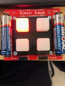
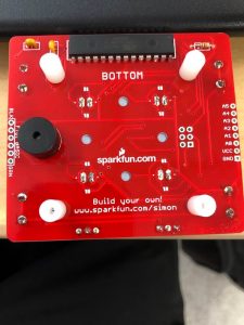
Starter Project: Simon Says Game