Serial.println(“Hello, world!”);
Output: Hello, world!
My name is Geoffrey and I am a rising sophomore at San Mateo High School. During my time at Bluestamp, I built a digital multimeter and a robotic arm. Check out those projects below, and documentation for the arm is included if you want to build your own.
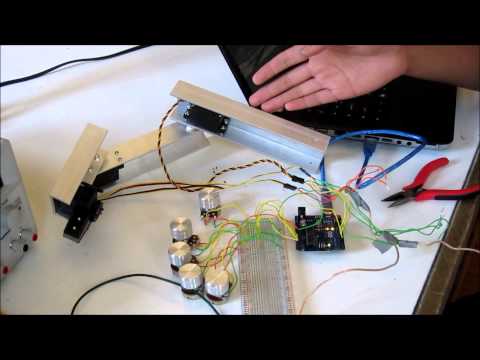
Here is a nice picture of my robotic arm:

Documentation
BOM: http://bluestampengineering.com/wp-content/uploads/roboarmBOM.xlsx
Code: https://github.com/gding/roboarm
Mechanical drawings: http://www.flickr.com/photos/99069175@N06/sets/72157634684484095/
Schematic: http://bluestampengineering.com/portfolio-view/geoff/attachment/roboarmschematic/
Torque calculations and example: http://bluestampengineering.com/wp-content/uploads/Torque.docx
Everything above in original format (.xlsx, .ino, .ipt/.iam, .sch, and .docx) in a zipped folder: http://bluestampengineering.com/wp-content/uploads/Roboarm-documentation.zip
The inspiration for my design was from another BlueStamp Student, Ariel Z.
Main Project: Robotic arm
Hello World.
My main project is a robotic arm controlled by potentiometers. This project took up all of five weeks of Bluestamp, between waiting and working. The project itself is not too complicated, but did require a large amount of machining to be done. A video, including an explanation, of what my arm does and how it works can be found below.
Mechanical Engineering
Excluding electrical, electromechanical, and fasteners, all other parts were custom machined. I purchased a three-foot length of aluminum U-channel and cut it into five pieces of length 8, 8, 4, 2, and 2 inches. The eight-inch segments were used for the upper and lower arm, while the single length of four inches was used for the wrist. Finally, the two two-inch pieces were used to mount the base servos (shoulder) to the base. The base was cut out of three twelve-inch squares of wood and screwed together.
Electrical Engineering
The wiring appears complex but is really quite simple. The potentiometers are wired to +5V, ground, and each to its own analog input pin on the Arduino. The servos are powered by a DC power supply, though I am planning to use a 5VDC adapter to allow the arm to be plugged into a 120VAC wall socket, and are controlled by PWM output by the Arduino. The Arduino is powered by a computer for now, but it will be powered from a wall socket as well in the future.
Computer Engineering
The code is quite simple as well. I used the servo library for Arduino by Michal Rinott to control my servos with potentiometers. The code reads an analog input from the potentiometer, converts the 10 bit integer to a degree value for the servo, and sets the servo to said angle.
Conclusion
Over the course of six weeks at Bluestamp Engineering, I have learned and relearned many things which I had forgotten before. Most of my newfound knowledge relates to electrical engineering and what our various speakers have said. I have had a great experience here at Bluestamp Engineering and would highly recommend this program to anybody interested even remotely in engineering.
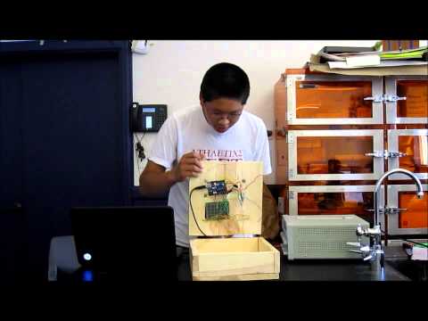
Milestone One: Lower arm, wrist, and hand functioning
Hello World.
For my final project, I am building a robotic arm that is controlled by potentiometers, or variable resistors. Today, I reached my first milestone. I successfully connected the lower arm, wrist, gripper, and all involved servos together. Everything works quite smoothly. As seen in the video below, I can pick up light objects such as a pencil with my arm. My next step will (obviously) be to build the rest of my arm.
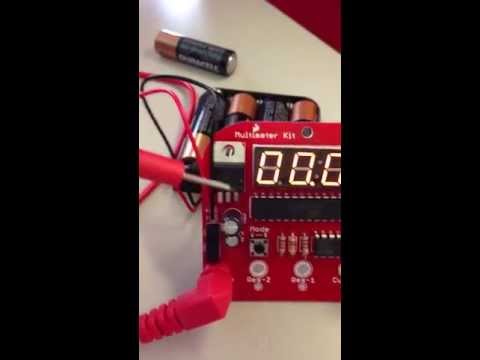
Starter Project: Digital Multimeter
Hello World.
My starter project was a digital multimeter (hereinafter referred to as a DMM) from Sparkfun Electronics. A digital multimeter is a digital (hence the name) device that is generally used to measure voltage, amperage, and current. Some more advanced functions include, but are not limited to, capacitance, temperature, and continuity. I chose to build this item because DMMs are very useful tools for anybody working with electronics. The multimeter I built with the kit from Sparkfun can take the aforementioned general measurements of current, voltage, and resistance. In retrospect, I probably should not have soldered the battery connections to the printed circuit board, but there isn’t much point in desoldering now. For more information about this project, including what each part does, see the video below.