
Hi! I’m Gedalia and I am a rising sophomore at Westchester Hebrew High School. All of my life I have been interested in building and designing, whether it’s origami, Legos, or building my project, here at BlueStamp. Almost half a year ago I started looking for camps that I could do over the summer, and I knew I wanted it to be something with biology or engineering. After months of searching for the “perfect” camp I came to the conclusion that there was no such thing. A few weeks after this, my friend told me about this engineering camp he was planning on going to that was supposed to be very hands and different from many other engineering camps, because with others, you built a kit, but with this one, you camp up with your own personal project. This came to as perfect as I could think of according to my standards.
This camp was of course BlueStamp. I was a bit nervous coming here, being that I did not have much of a background with robotics or programming, but after being here for six weeks, I could not be happier with my camp choice. I have learned and gained so much from this summer, and hope to be able to share a little of that with you, fellow reader.
I chose to make a PS2 controlled tank for my intensive project because I was interested in learning more about coding, as I would do a lot of this when controlling the motors remotelly, and I have always interested in cars and motors. This project combined the two fields, which made it an ideal project for me.

![]()
![]()
![]()

Build Plan:
- Check for all parts
- Build gearbox and attach to chassis
- Assemble wheel and track kit
- attach to chassis
- Attach chassis to arduino
- Plug in lithium battery to arduino and test motors
- Program arduino motor shield for speed of motors
- Program ps2 controller to control tank/arduino
Final Milestone:
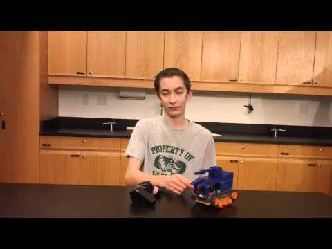
For the final part of my project I designed and printed a 3D enclosure for my tank to hide the wires, and make the tank look more like a tank. Some of the problems that I encountered were measuring the dimensions for the enclosure and securing it to the arduino. It was difficult to make the walls of the enclosure the right size because if they were a millimeter thicker than I wanted they would be too thick, and if they were a millimeter too thin, they would be flimsy and break.
The first time I printed the walls of the enclosure this happened and they broke immediately. Also I had to redraw my entire design because I could not print it as a one part, but as several that I would later glue together. Even though I had to redesign it, I think it came out nicer with some of the changes I made the second time around, than if I could have printed it initially.
Now not only can it move around and climb obstacles like a tank, but it has the look and feel of one.
RC Tank: My First Milestone:
Over the past few weeks I have been building a PS2 controller controlled tank. Here I will share my experiences and learnings. I got my library, which is a collection of functions and commands that can accessed when writing code, and based my code off of Bill Porter’s1 and Paul Bleisch’s2 websites.
2(http://paulbleisch.com/blog/2013/01/03/simple-remote-controlled-arduino-tank/)
You can find my bill of materials below. The first part of my project was building the gearbox , which is an assembly of gears that based off how they are put together will influence the speed and power of your motor, as well as the direction of the axle it’s spinning; then follow the directions to build the 114.7:1 type gearbox. That number is called a gear ratio, and what it means is that for every 114.7 revolutions the gears spin, the axle spins once. The directions are a bit hard to follow but you should be able to figure them out . This is my recommended gear ratio for this tank; it’s a bit slow, but very powerful.
Next I mounted the motor to the chassis. I unboxed the chassis and counted the long way three and a half holes down, marked this spot, and then counted two more holes down and marked this spot. I then did to the other side of the chassis and cut out the area I previously marked. The gear box instructions shows in grey where I needed to cut. Following the instructions in the box, I built the track and wheels set, and mounted the wheels under the chassis.
I cut some jumper wires to connect the motor terminals to the motors and 3-D printed some spacers to connect the arduino to the chassis because I could not find any online that would be the right size.
I got the instructions for connecting my arduino to the wireless receiver from Bill Porter’s website. (http://www.billporter.info/2010/06/05/playstation-2-controller-arduino-library-v1-0/) They are very straightforward and easy to understand.
I then downloaded the library to control the tank from the ps2 controller, from Bill Porter’s website and downloaded the library labeled DOWNLOAD PS2X and opened it in arduino. I also got the code from Bill Bleisch’s website and modified it a bit; mainly changing the pins he used to what the pins that I used for connecting the arduino to the wireless receiver.
After uploading my code to the arduino, I plugged in my LiPo battery to the JST port on the arduino, turned on the PS2 controller, made sure the batteries were in, and waited for the lights on the PS2 controller to come one, which they didn’t. This was due to that I needed to press start and select. Then I was able to move the tank around and found that these were the controls:
Right track forward: L1/L2
Left track forward: R1/R2
Both motors spin backwards: L2 → R1 → R2
To spin clockwise: R2 → L1
To spin counterclockwise: L2 → R1
To go forwards: R1/L1 → L1/L2
I encountered my worst problems after I was finished with the basic controls. I tried adding a GPS module shield onto the arduino, causing my computer to crash. Upon restarting my computer and trying out the tank again, it was not working. After weeks of experimenting with fixes, it finally came down to adding a 10k resistor between data and power (5v) for the wireless receiver. I needed to use the prototyping section of your board and make a solder bridge between the power wire that goes from the wireless receiver and the 5v pin. I also needed to make a solder bridge between the data pin on the arduino and the wireless receiver. Then I soldered the 10k resistor, one end soldered to the data wires, and the other end soldered to the power wires.
Another problem I ran into was that my dualshock ps2 controller stopped working. I ended up getting a third party one, which ended up working. Another factor that contributed to my problems was that in the code, one of the section that controlled speed of the motors (E = 4) needed to be changed to E = 8. The E is just a name I gave to one of the motors and the four and eight mean what pin in the arduino the motor is using for it. The problem was that my arduino did not support pin 4 for that function.
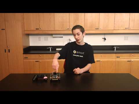
Mini-POV Tutorial:
A mini-pov is a device that has a column of LEDs that blink rapidly in a sequence. When the mini-pov is waved quickly back and forth it looks as though it is displaying a message that you have customized and programmed into it. In reality, it is just a row of LEDs that while blinking and being waved, give the illusion that they are forming a message.
These are the parts you will need:
- Mini-Pov Kit http://www.adafruit.com/product/20
- Usb Serial Adapter (only if your computer does not have a serial port.)http://www.amazon.com/dp/B00J4N9T9C?psc=1
- Two AA batteries
Follow this guide to solder the parts together. (https://learn.adafruit.com/minipov3/solder-it) It is pretty straight forward. When soldering, make sure that the iron is hot, and then heat the wire (try not to touch the board) for around two to three seconds. Then place the solder on the board on the wire that you just heated until you see the solder form a mound which seals the wire to the board. Upon the mound being formed take away the solder and then the iron. The point of soldering is to electrically glue the wire to the board, or in some cases, wire to wire, thereby allowing the electrical current to flow.
To give you an understanding of what you are using here are some definitions:
Semiconductors: are devices that act as a path, which an electrical current through, that connects an insulator-something non-conductive- and something conductive.
Resistors: are semiconductors that restrict the flow of an electrical current. These are the little ovular devices with stripes on them- stripes represent the amound of resisistance.
Diodes: are semiconductors that force the flow of an electrical current in one direction. These are the little red devices. LEDS (light emulating device) are a type of diode that let off light.
Microcontrollers: are devices that store data or a program that will tell its effectors what to do. This is the device that looks a bit like a centipede.
A problem that I encountered was that the black and red wires didn’t have enough wire sticking out so when I soldered it into circuit they later fell out. I recommend to strip the wires down a little bit so there will be more wire to work with.
When you have completed soldering, follow this guide for preparing the software only until you switch the delay from 2000 to 5000. (https://learn.adafruit.com/minipov3/software) Even though this step is optional I still recommended it because it will increase the delay between your computer sending information, and the microcontroller receiving it- this might help you if you are getting errors. It means that your microcontroller cannot keep up with the information that it is receiving. If you don’t have a usb serial port, make sure to plug your usb serial adapter in your computer here, as well as plug your minipov into the adapter. Make sure your minipov is on.
The largest problem that I had, was with the uploading of their pre-written .hex (minipov.hex). I could not get their file to upload onto onto my mini pov. I continually got this error message:
avrdude: verifying…
avrdude: verifying error, first mismatch at byte 0x0000
0x12 !=0x00
avrdude: verifying error; content mismatch
avrdude: safemode: Fuses OK
avrdude done. Thank you.
make: *** [program-minipov] error 1
C:\
Skip uploading their .hex file, it doesn’t work. Rather go on to this tutorial (https://learn.adafruit.com/minipov3/customize) and write your custom message – I recommend using this site for writing your message http://www.repulsor.net/minipov/.
Another variable that could have been the problem was that arduino files had been installed on the computer, in addition to AVRDUDE. When I gave the computer the command make program-minipov (this is to upload adafruit’s files) Arduino may have been interfering with communications between the computer and the microcontroller, because the computer has different ways of communicating to Arduino and AVRDUDE. To accommodate this, the arduino files were uninstalled which may have stopped the interfernece, thereby letting the program run.