
Line Following Robot
This is a robot which follows a line by using IR sensors which differentiate between light and dark to help navigate and stay on the correct line.
Engineer
Gabi M
Area of Interest
Biomedical engineering
School
SAR High School
Grade
Incoming Junior
Final Milestone!
(I used the L298N.h> library which I downloaded online)

#define SEENOTHING 0
#define SEESOMETHING 1

const int LSensor = 2;
const int RSensor = 3;
int inputVal = 0;


// 1 = nothing
// 0 = something there

#define ENA 9 //pin definition
#define ENB 11
#define IN1 10
#define IN2 8
#define IN3 13
#define IN4 12

//motor instance
L298N motorRIGHT (ENA, IN1, IN2); //rt when facing top sensor
L298N motorLEFT (ENB, IN3, IN4); // left


void setup()
{
  pinMode(RSensor, INPUT);          // Pin 13 has an LED connected on most Arduino boards:
  pinMode(LSensor, INPUT);   //Pin 2 is connected to the output of proximity sensor
  pinMode(IN2, OUTPUT);
  pinMode(IN1, OUTPUT);
  pinMode(IN4, OUTPUT);
  pinMode(IN3, OUTPUT);
  pinMode(ENA, OUTPUT);
  pinMode(ENB, OUTPUT);

  motorRIGHT.setSpeed(150);
  motorLEFT.setSpeed(150);

  Serial.begin(9600);
}

void loop()
{
  inputVal = digitalRead(LSensor); //READING VALUE OF LEFT SENSOR
  Serial.print("LSensor ");
  Serial.println(inputVal);
  inputVal = digitalRead(RSensor); //READING VALUE OF RIGHT SENSOR
  Serial.print("RSensor ");
  Serial.println(inputVal);
  delay(500);// wait for half a second

  if (digitalRead(LSensor) == SEESOMETHING && digitalRead(RSensor) == SEENOTHING)   //TURNING LEFT
  {
    motorRIGHT.forward();
    motorLEFT.backward();
    delay(200);
    motorLEFT.stop();
    motorRIGHT.stop();
  }
  else if (digitalRead(RSensor) == SEESOMETHING && digitalRead(LSensor) == SEESOMETHING) //STOPPING
  {
    //tell the motor to stop (may depend by your wiring)

    motorLEFT.stop();
    motorRIGHT.stop();
    delay(200);

  }
  else if (digitalRead(RSensor) == SEESOMETHING && digitalRead(LSensor) == SEENOTHING)   //TURNING RIGHT
  {
    motorRIGHT.backward();
    motorLEFT.forward();
    delay(200);
    motorLEFT.stop();
    motorRIGHT.stop();
  }
  else
  {
    //tell the motor to go forward
    motorRIGHT.forward();
    motorLEFT.forward();
    delay(200);
    motorLEFT.stop();
    motorRIGHT.stop();
  }
}
Now that I have completed the code and perfected the placement of the sensors, my robot is able to follow an intense curved line, and is able to reorient itself along the way to follow the line properly. The code is available on the left under the “Robot Code” toggle.
REFLECTION:
Over my time at Bluestamp I encountered many challenges, however with hard work, determination, and newfound problem solving skills I was able to overcome them. I encountered tough times while soldering some wires in order to install switches for the battery packs, and I also struggled with writing the final code. Once I tried to first write in pseudocode, I was then able to transfer that easily into real, working code. I learned so many new techniques and new facts about engineering that will most definitely help me later in life!
Second Milestone
To power the motors of my robot I used an L298N motor driver. This is necessary since the Arduino does not have enough power alone to fuel two motors and the motor driver has the ability to provide more current. This motor driver is a dual H bridge which is special since it allows for the control of direction and speed of two DC motors at the same time. An H-Bridge circuit contains four switches with the motor at the center, so the configuration actually looks similar to the letter ‘H’. by activating 2 switches at once you can change the direction of the current flow, thus changing the direction the motors are rotating.
I also had to write the code so that the H-bridge would be able to function, so I had to set speeds for each motor and command the motor to stop, drive forward, and backwards through the use of different commands spread out by delay functions. The H bridge is what allowed for these motors to work simultaneously, so I had a problem getting my motors to work and I knew it was not syntax, I had to strengthen the connections to the bridge so that both motors could function. The code which I am currently working on (which will allow the motors to move based on the signals detected from the IR sensors) together with the working DC motors will let the line following robot fully function!
First Milestone
Milestone 1 pictures
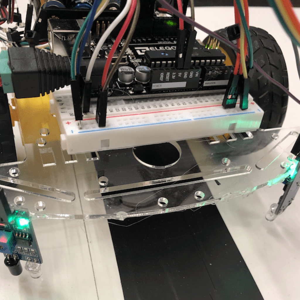
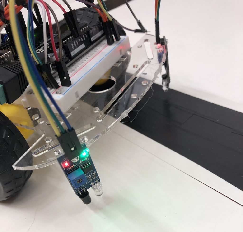
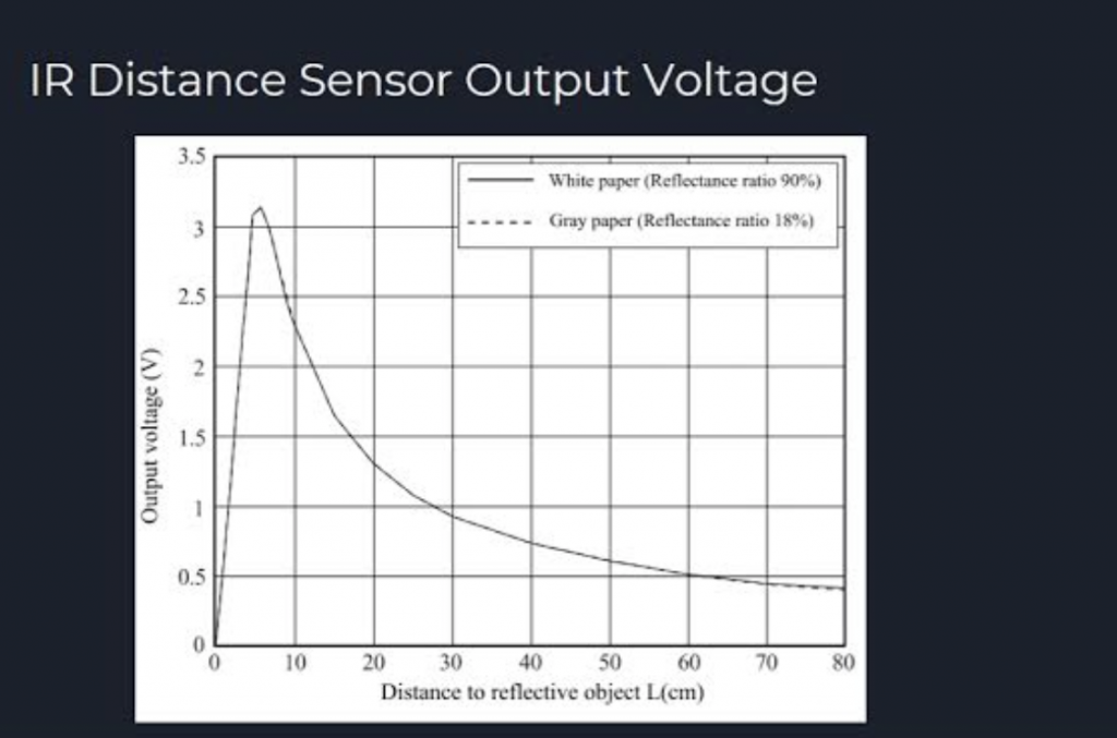
I assembled the chassis, connected the IR LEDs, and coded them to direct my robot when using the finished product. The IR sensors transmit and receive light and work together to detect whether anything is in their proximity, which helps the robot know to follow. These IRs are used for transmitting and receiving signals by utilizing the infrared light they emit. When these infrared rays falls on white surface, they are reflected back and picked up by the receiver which generates some voltage changes. When IR light falls on a black surface, light is absorbed by the black surface and no rays are reflected back, thus the IRs do not receive any light or rays. It is necessary to use infrared sensors instead of ultrasonic sensors since IR detects if there is a reflection with light, however ultrasonic rays only detects whether there is an object in its path using sound waves— it would pick up dark and light but the IR sensor is able to tell the difference so it is clear that it is better for this project since it is based on differentiation between dark and light.
Starter Project: TV-B-Gone
HOW IT WORKS!
I built the TV-B-Gone kit, which acts as a universal remote for any television through the use of a micro-controller chip and IR sensors.
