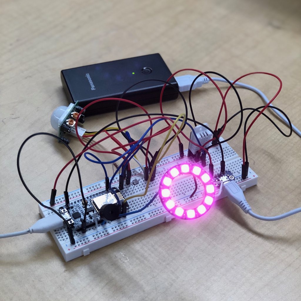
Smart Lamp with IoT Technology

A fully color-customizable smart light with sensors that detect environmental parameters using IoT technology.

Engineer

Forrest L

Area of Interest

Computational Finance

School

Monta Vista

Grade

Incoming Senior

External Links

Reflection

Demo Night Video - Forrest L.

During my six weeks at Bluestamp Engineering, I learned a lot of skills that I never would have the opportunity to learn in a classroom setting, which include  coding with the Arduino IDE, dremeling, soldering, and much more! Most importantly, I gained a newfound interest in mechatronic and electrical engineering, and hope to further pursue it by building passion projects in my free time.


As for my project, I plan to further add more features to my LCD fixture. I will add a button to the top of the box that will allow for me to call a new display screen to display on the LCD that has new widgets, such as customized stocks and calendar events.

Final Milestone + Modifications

Final Milestone + Modifications Video - Forrest L.

In my third and last milestone, I finished assembling my acrylic box, painting, dremeling, and drilling compartments and cutouts for each of my sensors. On top of that, I also hit my first milestone, which was to add an LCD fixture that displays customized text. I did some final testing and adjustments to a couple sensors, and actually realized that my temperature sensor was actually a DHT22, not the DHT11 I had originally thought it was!


The small obstacles I faced were mostly in regards to assembling the box without any wires snapping,which happened a couple times. To fix them, I hot glued my power and ground rails down onto my PCB, so they would be permanently attached to the PCB, and then resoldered wires, using heat shrink tubing to wrap exposed wire. I was also trained to dremel and drill into the acrylic, and learned how to execute LCD commands through Arduino JSON 6, as well as using NTP servers, plus getting live weather using openweathermap’s API.


The image on the left shows me while testing out my LCD when wired to the PCB. After testing out the LCD fixture, I assembled all the components together to finalize my project.

Second Milestone

Second Milestone Video - Forrest L.

In my second milestone, I successfully transferred all my wires and sensors to a PCB, which allowed for my project to be organized and compact. After transferring my sensors, I began cutting wires and placing them into the correct plated through holes. In the process, I connected my ESP8266 to Cayenne to check for any issues, but thankfully there weren’t any.


I only had to resolve small issues in my second milestone, and they were in regards to desoldering. The components and functions of all of my sensors have not changed from my first milestone, as what I accomplished did not involve any electrical or mechatronic engineering, just a transfer of parts. For my next and final milestone, I want to assemble my entire project into an acrylic container, then cut gaps for my sensors and light to come out of.


To the left, the first image is the wiring of my PCB, which is similar to my breadboard’s wiring, but more compact. The next image is of the backside of the PCB, and shows the solder bridges that I created to connect the wires to each other and the 5V and ground rails I created. The third image is a general overview of my project, with all components present, with the fourth being my hand-drawn schematic outline for my PCB, and lastly the digital schematic for my PCB.

First Milestone

First Milestone Video - Forrest L.

My first milestone consisted of assembling my sensors and wiring them onto my breadboard, then testing them all in my online IoT device platform, Cayenne. The neopixel ring turns on when the threshold of light captured through the photoresistor is below the amount set into code, and can be adjusted within the Cayenne dashboard, and the piezo buzzer turns on when motion is detected and reported into the dashboard from the PIR sensor (passive infrared sensor). The DHT22 keeps track of temperature and humidity data, returning the values to the ESP8266, and eventually the Cayenne dashboard. Lastly, the NodeMcu ESP8266 controls the entire breadboard through code from the virtual Arduino IDE and is powered through my USB breakout board.


I had many issues when initially building my main project, such as IDE library issues, IoT connection issues, and fried parts. My first issue was with the code, as the libraries wouldn’t upload into the Arduino IDE, and after some troubleshooting, I was able to resolve that by accessing Github repositories. Then came the connection issues with Cayenne, as my board was connected to my computer but could not access the virtual environment, which was resolved through using hotspot connections. I was also given the wrong power supply, 12V instead of a 5V, which fried my neopixel ring, as well as messed up the rails of my breadboard, which I had to replace.


To the left, the first image i the schematic that I followed to wire my breadboard, and the second image shows the Cayenne environment that the ESP8266 accesses. The last three image shows my Neopixel ring displaying a pink color.

Starter Project

Starter Project Video - Forrest L.

My Starter Project was a night light that used an Arduino, as well as a potentiometer and photoresistor, to control and change the colors of an LED. The night light turns on when the amount of light detected by the photoresistor is below the threshold set into the code, otherwise it appears white. Once the LED is on, the user can turn the potentiometer to change the current running through the resistors, which alters the color of the LED; from red to magenta.

Major roadblocks I faced with my starter project were in regards with the time I spent with a malfunctioning breadboard as well as with the LED cathode. With the breadboard issue, I spent time looking over my wires to make sure the pins were in the correct location. After that, I took more preliminary steps to see where the issue would lie. I then used a multimeter to see if the resistors or if the board were not conducting power. That was the issue and then I replaced my breadboard, which then worked! Following that, the next issue was with the LED itself. It would not work when plugged into ground, so then changing the wire placement to the 5V rail worked, thus I concluded the LED was not a common LED, but an LED cathode. This meant that all the RGB values displayed were reciprocal to what they were supposed to be, and after a bit of research I was able to resolve this issue to finally get a working project.

Leave a Comment

Start typing and press Enter to search

Bluestamp Engineering